In this post I have explained a simple laser GSM call alert security circuit which immediately calls the master as soon as an intruder is detected through a laser beam interruption.
The idea was requested by Mr. Roldan.
Circuit Objectives and Requirements
I am not an electronic engineer, but I can manage to troubleshoot minor electronic problems. I also have a basic knowledge on electronic schematics. I have already scans all your schematics about cell phone projects, but still I did not found the right project I wanted to build.
My request :
1.) A security alarm (i.e. burglar alarm) using laser, once that an intruder lurks in the perimeter it will eventually trigger/dial my cellphone, same as the idea of your CELL PHONE DOOR LOCK CIRCUIT. Instead of pushing the car central lock instrument, it will dial my number thru a GSM cell phone. so that I am aware that somebody is/were inside my house. I am always away from my house.
2.) I am thinking about using 2 cell phone, 1 unit is for the alarm system that will dial me in case of an intruder is inside.
Hoping for your kind consideration about my request sir, till next.
The Design
In one of my earlier posts I have already presented a Cell Phone Call Alert Security System Circuit designed to alert the user whenever an intrusion was detected, it employs the IC 4060 for the procedures. This circuit was inspired from yet another earlier article titled car GSM security circuit.
The present design also is based on a similar principle, however it utilizes an IC 555 and a small delay timer for implementing the functions making the circuit much simpler than the earlier concepts.
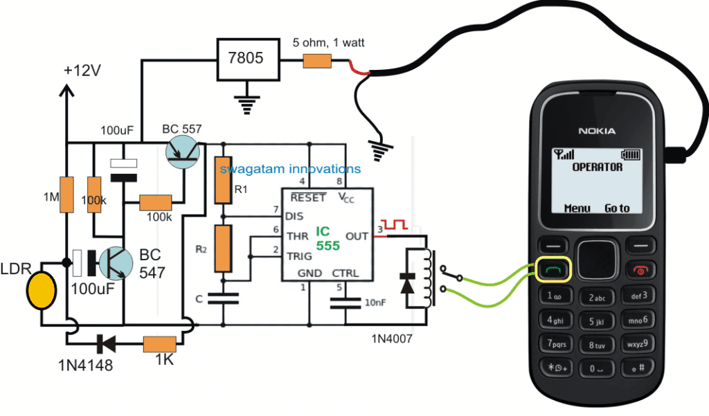
The following diagram shows the detailed configuration, let's try to understand it further through the given explanations:
The Delay Output from IC 555 can be obtained by solving the following formulas:
On Time Output = 0.7(R1 + R2)C
How it Works
Referring to the above shown laser activated GSM call security circuit, we can see that the IC 555 is configured as a standard astable.
The 555 astable is powered through a delay OFF timer circuit which is in turn attached with an LDR trigger.
The LDR is supposed to be focused with a laser beam aligned across the restricted zone.
As long as the laser beam remains focused on the LDR, the resistance of the LDR is held sufficiently low with respect to the associated 1 M resistor.
However in an event where the laser gets interrupted, which might happen while an intruder tries to trespass the restricted zone, the LDR suddenly experiences a high resistance allowing the transistor BC547 base to acquire a triggering pulse through the 1M resistor and the associated 100uF capacitor.
This in turn activates BC557 hard into conduction and simultaneously charges the upper 100uF capacitor to the optimal limit.
Once the above takes place the BC547 is no longer required to conduct and in fact it stops conducting due to its base 100uF capacitor acquiring full charge and/or due to the restoration of the laser beam on the LDR (as the intruder crosses over to the other end)
The BC557 continues to conduct from the charge accumulated in the upper 100uF, and powers the IC 555 such that it is able to produce around three pulses to the relay which responds to this and clicks thrice and then stops.
The above three pulse limit may be achieved by suitably adjusting the two 100uF capacitor values such that the delay timer conducts for a period just enough to allow the IC 555 to produce those 3 pulses, after which the BC557 may be expected to switch OFF, along with the the IC 555 and the relay.
R1, R2, and C1 may also need to be calculated for allowing 0.5 second pulse from the astable, meaning the 3 pulses should not take more than 1.5 seconds to complete
The relay contacts can be seen integrated with the "call button" of a mobile phone which is used here as a cheap alternative to a GSM modem, although the cellphone works more effectively and is much cheaper.
The cellphone's phone book is initially stored with the owners number and is manually called upon once which sets the number as the first number in the calling list.
Subsequently now whenever the green button is actuated thrice enables the cellphone to begin calling the owner's number.
The above basic principle is efficiently utilized for alerting the owner whenever an intrusion is detected through a laser beam interruption.
In the above proposed laser activated GSM call alert security circuit, the modem cellphone employed is a NOKA1280 which happens to be the cheapest and easy cellphone and therefore becomes perfectly suitable for this application, although any other similar cellphone could be tried for the same.
The integration of the two wires with the call button of the cellphone can be quite tedious since the keypad of this phone has no solderable pads, and therefore the wire ends might need to be tightly pressed on the relevant pads and secured with some kind of glue for reinforcing the contact in the position permanently without loosening, overtime.


Questions & Answers
Namaste sir.
Is it possible to build a buck converter using aurdino? Output voltage needed is around 100 volts. lf yes, then can you please guide regarding this?
Hi Vani, yes that’s possible but using an Arduino for a buck converter would be an unnecessary overkill.
By the way what will be the input voltage?
Sir l have thought of giving input as 200V. Can you please guide me in doing this sir? I will be glad if you could help sir. Thank you.
Vani, can you provide the maximum output load current specifications? If possible I will try to figure it out.
Sir l am unaware about the specifications of the load current. What maximum output current can be expected for 100V output sir? Please guide me sir.
Vani, the requirement will depend on what load you want to use and the maximum input current capability.
You can have any magnitude of current you want, and may need to configure the circuit accordingly.
For further conversation please comment under any buck converter article:
https://www.homemade-circuits.com/?s=buck+converter
Can we use Motion sensors instead of LDR? May be like 6 motion sensors.
LDR cannot be replaced with motion sensor in this design
I can’t believe you are still here after all these years. Thankyou very much. Will you be able to help me improve this with 6 Sensors . I want to make it work in a power outage also. Because in SriLanka we have power cuts.
Lets make it a possible to operate under a powercut.with a 12v tuktuk battery.
Lets add 6 motion sensors and and a 12 V car alarm which goes off for only 1 hour.
And ability for owner to call back the telephone number of the security system and turn off Alarm !
Hi, thank you for being an avid reader of this blog. I will consider the improvements you have suggested, and if “possible” try to design the required circuit.
Thank you kindly good sir.. let me suggest a couple of more things to make it even more better.
The battery idea does not have to be a tuk tuk battery, it can be a rechargeable lithium battery if you think its easier so we can use household Ac with a 12v adapter and DC when power is out.
I also like to have a 0-9 number keypad to use password to both turn on and turn off the alarm system. Before going out of house. ( If possible the password can be changed to whichever i prefer) 🙂
The keypad stays inside the house too. (where sensors are placed)
I shall Have a 30 second delay after turning on the system to quickly go out and lock the door.
Also if motion is detected- the alarm system shall have 30 second delay before going off. ( Which means i can come into house and use the keypad to turn off system)
if if i build this. first one i am going to gift is to an Ashram and send you all the good energy.
Thank you. Blessings.
-kona
Thank you Kona, for your interesting suggestions. I appreciate it very much. I will surely try to figure them out when I have time.
Thanks for this great idea in the world of Technology
Thank you, appreciate your kind feedback!
Hola me ah tocado Realizar este circuito como proyecto de unidad, pero mi pregunta es: Cuales son los calculos que deberia sacar de este proyecto. El ingeniero nos puso que debemos sacar los calculos pertinentes dle circuito me puede ayudar con eso.
Hi, adding calculations to the circuit may not be difficult, but attaching the relay wires with a cellphone call button can be the real complex part.
Hi there. Interesting subject.
In early 2000 I worked on something very similar. Subtle differences though. I built a very simple 2 second timer activated by a PIR/ Infrared-Beam. The relay output was connected to the number 2 button on the cell phone’s ‘speed dial’ function. In other words, when the beam is triggered, it is like pressing the speed dial on the phone. The LDR on an extension of the circuit (also straight forward) was laid over one of the LED’s on the phone key buttons. This meant that I could also phone the ‘alarm’ cell phone to activate a second relay. This worked well on my automated gate motor and managed to set up my phone’s voice dial command to open my gate at home. Note: This was long ago and I initially designed this as a stock theft alarm system (during my days in the South African Police Force). The unit could be deployed on a farm or in the bush-veld with a standard alarm battery which lasted several days/ weeks. I have since forgotten all the specs and will gladly utilize your example to play with this idea again. I had a call from a friend who is still involved with farm attacks and stock theft who contacted me today…will pass your weblink onto him. Thanks for your awesome work.
BUEN TRABAJO.
Amazing! Your idea looks so similar to this. Let me know if you need any assistance in this regard, will be happy to help!
Thank you! Your help will go a long way.
I have somehow been roped into a group to assist with an early warning system which can be deployed in high risk areas to assist farmers.
*The system should be stand-alone and battery operated
*Low cost is a major factor
Whatever device used to trigger the alarm (PIR/Laser/trip wire) should report to a circuit connected to a GSM device similar to the SIM 800 or SIM 900 (never worked with this, so I’m guessing – perhaps there are cheaper alternative devices available).
First prize would be for the system to report to multiple smart phone devices where users have an App to monitor incoming alarms. Not sure if there’s a suitable app on Google Play perhaps.
So in short;
Example – Laser beam focused on LDR is triggered by intruder. Receiving LDR circuit triggers GSM module to notify end user/s via their Smart Phone App. (Laser would be the most cost effective way to go – but I am open to suggestions).
The goal is to have a circuit diagram designed in order to eventually print in larger numbers to reduce cost. It should be simple yet effective.
I sincerely appreciate your feedback and ideas.
Best regards
Wow this is great thanks. How would one go about replacing the arduino with a pcb for multiple production?
Is this done with a specific programmable IC and additional components? Just thinking on cost savings. Is the GSM module a specific type from the arduino manufacturer or can any gsm module be implemented?
Glad you liked it!. You can replicate the Arduino board items (except the connectors), and create the prototype over a desired PCB.
The IC specs can be found on the Arduino IC which can be used on the customized PCB.
The GSM module is universal, not specific to Arduinos.
Thanks! Will give it a bash.
OK, great! I think I already have this project ready made in this website. Here’s the link, you can check it out:
https://www.homemade-circuits.com/sms-based-laser-security-circuit-using/
Sir, can you please explain in more detail how to set up the wires with the call button in a way that it presses it?
Try, when you open the cellphone, you will find the PCB under the green button having a circular copper pad, one small circular copper pad surrounded by a circular copper ring like pad, the shown wires from the circuit will need to be connected with these two pads….but these pads will not allow soldering therefore you will have to arrange the connection by hard pressing the wires with these copper pads.
Thankyou so much for the quick reply sir!
you are welcome Try
Sir, I’m new to this and I have no i dea about the values of r1 r2 and c1. Can you please tell me if there is a specific range for them,is there a way to find them using proteus, how do I find them??
I see thankyou so much!
I see. Could you recommend me another circuit which is cool and yet easier than this one. Preferably, one which has the values of all the given components. I shall be much obliged.
This circuit is actually the simplest one, but the stages will need to be understood thoroughly before trying, and to ensure perfect results and success. If you are a newcomer you will have to study and understand the various parameters correctly, that will require some effort.
Try, The circuit above will require some serious setting up procedures if you are new then you might have trouble in completing it, I would recommend you to take an experts help while making the project.
I was talking about constructing the above schematic, please I am not a 100% expert, what value is good to be used as R1/R2 and C1? I am confused with replacing the values, thanks for understanding
this circuit is difficult and will require a lot of understanding, if you are a newcomer you should not try this, or try it at your own risk….R1,R2 C1 values will need to be experimented with great accuracy, I have explained the details in the comments.
OK sir, but I have good intermediate skills in circuit construction, OK as for the resistors, can I use a variable resistors so that I can adjust to the desired accuracy? Then about the capacitor, should I use ceramic or paper diletric
I look forward to hear from you
Nkwenti, you can use variable resistors for getting an adjustable option, the non-polar capacitors can be ceramic discs
Dear sir.
Do you have any laser schematic
Please provide more details regarding your design, I’ll try to help
Good day sir! Thank you so much for the great work you are doing to help us develop our knowledge of electronics.
Im just a hubby of electronics, I want to build this circuit but I dont know how to calculate R1, R2 and C1. Please guide me on how to calculate them. Thank you once again.
Adam M Abdullahi from Abuja Nigeria.
OK I will do that. Thank you so much
you are welcome!
Good day Adam, I have already explained the concept elaborately in the article and in the comments, please go through all those explanation for getting the required information…
Sir, greetings. I come across your website while following on Pinterest. I am learning Electronics and find it very interesting. I am a hobbyist from India.I look forward to your guidance in future. If any subscription based program is there, kindly let me know. Thanks a lot.
You are most welcome Ajay, you can feel free to post your queries in the comment section, I’ll ensure they are answered at an earliest.
Once your comment is posted you will be automatically subscribed to it, however the results might end up in your email spam box, so please make sure to white list the subscription to correct the issue.
very well done indeed … nice solution … but if i want to have a simple call alert while my door/window opens …. only by implementing " a reed relay & a magnet" i.e if a reed relay and magnet are implemented at the door such that … when door closes … magnet come incontact with the reed relay and makes it in Off or open position … and as mentioned the cheapest GSM phone dialing is connected to reed relay …. so if door opens … magnet moves away … causing reed relay to be in ON or short position, which activates the dialing of owners contact from the GSM phone …….. so kindly tell me … is it possible to implement and how will be its complete circuit please ????
Thanks Hammy, you are most welcome!
Hey thanks a million … it seems good … i will try to implement it sooner… take care n thanks again!
Thanks Hammy, it can be done by replacing the transistors stages in the above design with another IC 555 based monostable stage.
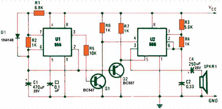
The following monostable circuit can be used with some minor modifications and its pin#3 output could be used for powering the above IC 555 astable circuit and for the sunsequent relay pulsing.
https://www.homemade-circuits.com/2016/11/intruder-position-indicator-security.html
In the above linked circuit you just have to remove the T1 stage and replace the T1 collector/emitter points with your reed relay terminals, and adjust the R3/C2 such that its pin#3 powers the IC 555 astable circuit for a time period that may be just enough to allow 3 triggering pulses for the relay.
a muillion thanks to you sir swagatam, im so overwhelmed that my request was granted.. ill try to build these as soon i am free from my hectic job schedule. God speed to you sir! (roldan)
You are most welcome Roldan, I wish you all the best!!
r1, r2,c1=?
you will need to calculate them suitably to enable the relay to produce the intended switching, and this must be in coordination with the delay period of the timer circuit…meaning the delay time should allow the 555 IC to produce only three clicks and then cut off the supply
hi swagatam cant these other light sources be used rather than laser beam, laser this side is quiet very expensive.
Hi Davis, other forms of lights will not work since they cannot be focused sharply from longer distances and in a straight line.