This super simple circuit design of a gsm car security system really works.Don't believe it? Find out and learn the simple method of constructing it. How would you feel if you had the power of controlling your vehicle through your own cell phone, from any part of the world? Learn more how to build a homemade gsm car security system.
Introduction
I always wondered how to become rich by inventing or developing an idea that may be simple in design yet breakthrough in its features.
Cell phones have always intrigued me for the simple reason that, these gadgets are so compact and sleek in appearance and yet are able to do the monstrous task of sending signals wirelessly across the globe within seconds.
One day it struck me - can there be a simple way of exploiting this outstanding feature so that it may be used as a “cell phone remote control” to operate any equipment by just a flick of a button from any part of the planet?
Since all the commercial gsm based remote controls use a modem for the purpose so why can’t a mobile phone be used as a modem?
Such a “modem” will be easy to acquire, user friendly, low cost and easy to install. Besides, the conventional types of gsm modems are costly, difficult to wire and require special SIM cards and prior intimation to the network providers for it to become functional.
Inspired by the brilliant idea and after a relentless hard work it was a true sitting moment of success when I finally was able to complete a reasonably good, very economical gsm car security system that could not only immobilize a vehicle and do central locking but also send a revert back call to the owner’s mobile phone in case of an intrusion.
The system is armed and disarmed through subsequent miss calls from the owner’s cell phone and no call costs are incurred during the process.
Exuberant with the successful venture, I decided to contact relevant companies for the promotion of the unit. But the news was really shocking.
These companies rejected my product saying that the design wasn’t “industrial” and the use of an attached cell phone as a modem was not acceptable.
Very dejected I tried to promote and sell the unit through my friends and relatives, but, the task was uphill since the operation demanded lot of initial investment and after-sales service, so finally, I had to drop the decision.
But folks, there’s a good news, I am ready to share the success story with you all and unleash complete details of this truly amazing circuit.
The circuit is very simple, foolproof, fail proof and mind you it’s already working perfectly in four of the vehicles and in one of the jewelers shops (as a security door lock) since last six months or so.
The Salient Features of the Circuit
Locking and unlocking of the vehicle is done through subsequent miss calls, thus no call costs incurred. The above operation may be done from any part of the world.
The engine of the vehicle may be stopped even when it’s in motion, from any part of the world. Vehicle Locked confirmation is done by rejecting the miss call while a continuous ring in the owner’s cell phone indicates that the vehicle has been unlocked.
Any quantity of phone numbers may be assigned into the system’s cell phone so that it responds and can be operated only through these numbers.
A break-in or an intrusion is effectively converted into a revert back call to the owner’s cell phone as a warning. The device includes a built-in automatic locking system, in case the owner forgets to lock the vehicle.
Prerequisite: A prepaid SIM card to be fitted inside the modem (attached cell phone module) An entire unit will cost you not more than $80 USD.
Warning: The unit will not work if installed in conjunction with some other form of security system already present in the vehicle. Let's move on to know exactly how to build this gsm car security system.
The Trigger Circuit
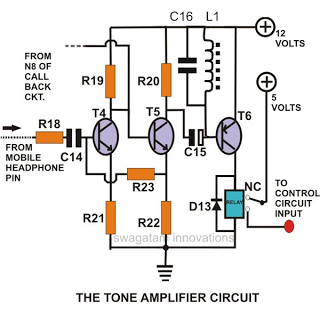
As shown in the circuit diagram, the small two transistor circuit forms the basic “beep once” tone amplifier coming out of the headphone socket of the cell phone.
As this ring tone is accompanied with a variety of unwanted glitches or strong RF disturbances, it became very important to stop these from entering the main control circuit.
These disturbances could easily rattle the entire circuit and produce bizarre results. Resistor R18, capacitor C16 and inductor L1 are all included just for the above rectification.
The amplified signal moves into a relay to energize it momentarily as long the tone persists.
The unit’s supply voltage is wired across the relay’s N/O contacts so that when it operates, a logic high signal is transmitted to the main flip/flop control circuit.
The employment of a relay ensures that it is operated only by a genuine ringtone pulse and not by any other obscure stray disturbance emanating from the cell phone (if at all they are able to break into the defenses of R18, C16 and L1).
PARTS LIST
All Resistors are ¼ watt 5% CFR, unless otherwise stated.
- R18- 100 ohms,
- R19- 22K,
- R20- 4K7,
- R21- 220 Ohms,
- R22- 1K,
- R23- 10K
- C14- 2.2μF PPC (PolyPropelene Capacitor),
- C15- 47μF/25V,
- C16 = 0.1/100V PPC
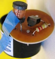
- L1 = 40mH, BUZZER COIL, OR THINNEST POSSIBLE COPPER WIRE WOUND OVER ANY FERRITE MATERIAL WITH 1000 TO 2000TURNS.
- Relay- 12V/400 Ohms
- Diode- 1N4007
- T4/T5 -BC547,
- T6- BC557
Alternatively, L1 may be retrieved from any standard piezo buzzer.....the example image below provides a clear view of the buzzer inductor:
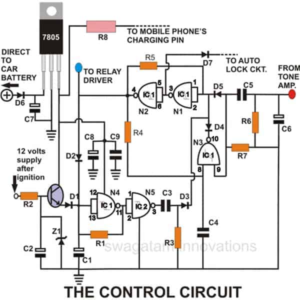
The Main Control Circuit
This circuit is basically a Flip/Flop circuit that toggles to alternately produce a stable logic Hi or a logic Lo in response to the input signal received from the above circuit.
I won’t go into a detailed circuit description as the particular circuit has already been discussed in one of my previous articles.
The out put of this circuit is used to activate/deactivate the ignition system and the central locking of the vehicle.
PARTS LIST
- All Resistors are ¼ watt 5% CFR, unless otherwise stated.
- R1/R7-1M,
- R2-10K,
- R3-39K,
- R4/R5-2M2,
- R6-10K,
- R8-22E(2W)
- C1-100uF/25V,
- C2-10uF/25V,
- C3/C4/C5-0.22PPC,
- C6/C7/C8-33uF/25V, C9-0.1PPC
- All Diodes are 1N4148, T1-BC547,
- Zener-4.7V/400mW
- IC1, IC2 = 4093
The Auto Lock Facility
The auto lock facility of this gsm car security system may be understood as follows:
Referring to the figure, as long as the output of N2 is high (system in locked position), the auto lock comprising of N4 and N5 is disabled and cannot operate.
The moment the output of N2 toggles low, N4 starts counting and after the set period of time (depending on the values of R1 and C1), the output of N5 goes high producing a trigger pulse at the input of N1, toggling it back to the locked position and once again disabling the auto lock.
Thus the system can never be kept in an unlocked position for more than the set period. Within this set period of time the owner of the vehicle needs to insert the vehicles ignition key into its slot to stop the auto lock from initiating.
Once the vehicle is locked, the ignition key will not work unless and until the system is unlocked through the owner’s cell phone.
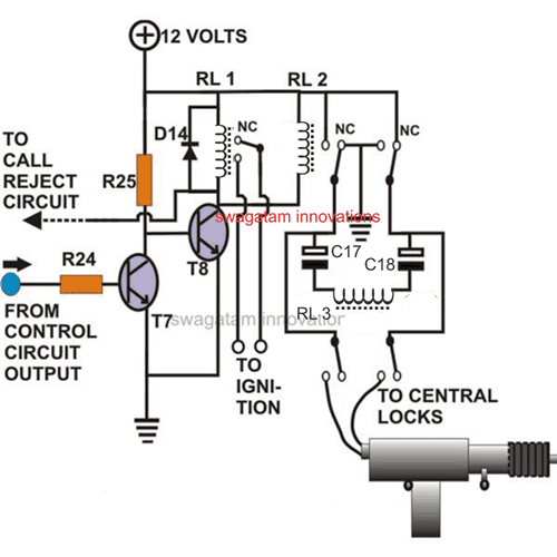
The Ignition Control Circuit and the Central Locking Circuit
As shown in the figure, it is basically a simple relay driver circuit comprising of R24, T7 and T8. T7 and T8 alternately makes and breaks the ignition relay contacts in response to the pulse received from the above circuit.
The central locking relay group is also rigged to T1 for a simultaneous operation with the ignition system. Central locking operation is responsible for locking and unlocking the doors of the vehicle (the car).
The central locking machine generally incorporated in car doors is actually made up of a DC motor operated through subsequent positive and negative momentary voltage pulses to alternately lock (push) and unlock (pull) the lever of the door respectively. Keeping this particular feature in mind the present groups of relays and the capacitors have been arranged to result in the above operation.
PARTS LIST
- All Resistors are ¼ watt 5% CFR, unless otherwise stated.
- R24-15K,
- R25-4K7
- C18/C17-470uF/25V
- T7-BC547,
- T8-D1351
- D14-1N4007
- RL1-12V/100 Ohms/10Amps.
- RL2-12V/100 Ohms/10Amps. DPDT
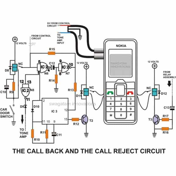
The Call Back Feature
Looking at the circuit diagram we see that the IC 4060 is wired in its basic oscillator mode. The coil of relay (extreme left) is connected externally to the door switch of the vehicle. In the locked position if the door is opened, the system takes it as an “intrusion”, momentarily activating the relay and triggering a monostable comprising of N6 and N7.
As a result the output of N7 instantly goes low resetting pin # 12 IC 4060 and it starts counting. Pin # 2 of the IC goes high after a few seconds and latches itself, but during this particular period of time its pin # 15 produces exactly 4 pulses and is used to operate a relay whose contacts are wired with the call button of the attached cell phone (modem) internally.
Therefore the cell phone starts making a call and the owner is immediately informed of a possible theft or a break in.
Now monostable N6 and N7 will release itself exactly after one and a half minutes, until this period of time the entire circuit will be “sealed” and will not respond even to the miss calls from the owner’s cell phone.
This feature has been purposely incorporated to ensure that the circuit is not disturbed when the attached cell phone (Modem) is trying to make a call to the owner.
PARTS LIST
- All Resistors are ¼ watt 5% CFR, unless otherwise stated.
- R9-10K,
- R10-2M2,
- R11-330K,
- R12-4K7,
- R13-39K,
- R14-1M,
- R15-1K,
- R16-330E,
- R17-1K
- C10/C12-100uF/25V,
- C11-0.001uFDISC,
- C13-47uF/25V.
- D9/D10-1N4148,
- D8/D11/D12-1N4007
- T2, T3 = BC547
- IC2 (N6,N7,N8)-4093
- IC3-4069
- Relays-12V/400 Ohms
The Call Rejection Feature
Another relay driver circuit as shown in the above figure takes care of the “call rejection” facility.
When the system is locked through the owner’s miss call, a pulse is sent to the base of the driver transistor which operates a relay momentarily.
Now since the contacts of the relay are wired across the “cancel” button of the attached cell phone (Modem), the received call from the owner’s cell phone is immediately rejected and a “network busy” is indicated in the owner’s cell phone confirming that the vehicle is securely locked.
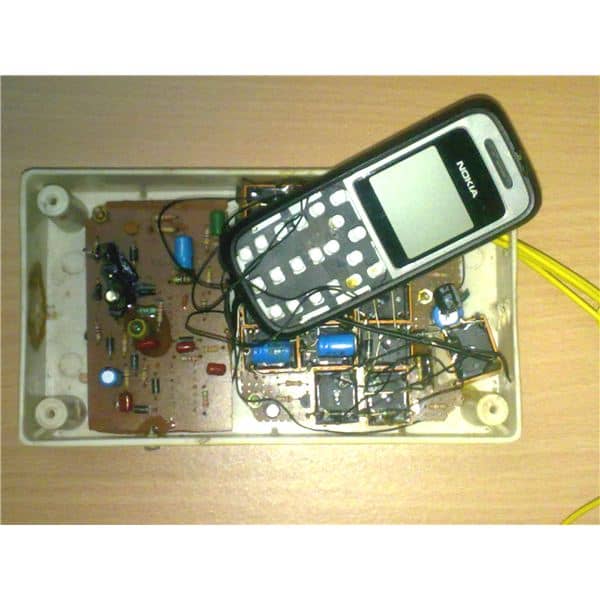
How to do the Internal Wiring to the Modem Cell Phone
The internal wiring of the modem of this gsm car security system may be understood as follows: You will have to do this part of the wiring very carefully and if you are not crafty enough, things can get pretty messy and spoil the whole “game”.
It would be better if you took the help of some mobile phone technician to complete the following operations:
It goes without saying that the outer cover of the cell phone is to be removed and also the inner metal mesh which is used to shield the keypads.
Carefully and very slowly peel off the keypad sticker and keep it in some secured place for later use.
You will find the embedded keypads exposed. But the sad thing is that the pads aren’t solderable, therefore the external wires from the relevant relay contacts cannot be attached to them through soldering.
So the only possible way is to fix the relevant wires by sticking there stripped ends to these keypads and let the keypad sticker and the metal mesh frame do the rest by firmly pressing these wires against the keypads to make a reliable contact.
The wires used may be the thin insulated ones, typically used to wire piezo transducers or simply a 36 SWG super enameled wire will do the job quite nicely.
Do not forget to “tin” the stripped ends of the wires so that they make good contact with the keypads.
Also remember to remove the small disc shaped metallic contacts in the sticker from the points which correspond to the cancel button and the call button. After this you may replace the sticker carefully back in its position so that it secures the connected wires further in there places.
Go on to fix the metallic wire mesh and screw it firmly to complete the “modem” assembly. The outer most plastic cover is not required, so do not try to replace it. This modem assembly is now ready and can be connected to the main circuit after the whole circuit assembly is over.
The Charger Section
The charger section of this gsm car security system utilizes a regulator IC 7805 and a current limiting resistor. It is connected to the cell phone modem permanently and is used to trickle charge its battery.
There’s no danger of overcharging the battery as every Nokia phone has a built-in self regulating automatic cut-off circuit.
Setting up the Attached Cell Phone Modem
Once the entire circuit assembly and all the connections are completed, the above cell phone modem may be set up through the following simple steps: Insert a pre-paid SIM card into the cell phone (Modem), Switch it ON the by short circuiting its “cancel button” wires externally using a piece of conductor. Since the keypads no longer exist, this is the only way to switch it ON.
Save the mobile phone numbers through which the unit would be operated. Go to the name section of all the above saved numbers – press options – Assign Tone – Select No Tone. Next, go to settings – Tone settings – Select empty (default ringtone switched OFF).
Similarly set the tone for the messages in the OFF position. Also switch OFF the keypad tones, warning tones and the start-up tone by selecting the relevant commands.
Finally, make a call through this modem cell phone into your cell phone by shorting its call button thrice externally using a piece of conductor, so that now the Modem "knows" exactly where to call back once a theft is sensed and will always call you back on this particular number every time the door of the car is opened (only when the system is in locked position). The Modem is now set perfectly and ready to use.
How to Test the Unit?
After concluding the whole assembly procedure as explained in the whole article, you may test this outstanding gsm car security system through the following simple methods:
Connect a good quality 12 volt regulated power supply to the circuit, The cell phone modem should immediately read "Charging", indicating that the charging process has initiated and is working perfectly.
Connect small 12 volt motor to the "central lock" outputs of the circuit. Start dialing the SIM card number, the moment your call hits the cell phone Modem, you will find the relays operating accordingly and the connected motor reverses its direction of rotation alternately on every subsequent calls made.
This confirms that the central lock section is operating perfectly and also the entire circuit.
Check the continuity of the ignition section using a DMM. It should make and break on every subsequent calls made. Similarly you may connect a horn (siren type) at the alarm output to check the relevant section.
The alarm should sound for a moment and stop at each and every received call by the modem. In the locked position (ignition relays in deactivated position), ground C10/R9's common point as might happen if the door of the car is opened (intrusion). The modem should immediately start calling the stored number and you will receive a call in your cell phone - the call back facility is working.
The above steps should be enough to confirm the correct operation of the system and you are all set to fix it in your car and actually witness the amazing feats.


Questions & Answers
Dear Swagatam,
Very impressed with your circuits. Seeing this car alarm alert system can it be modified to send a home alarm alert to my cell phone?.
Thank You,
Ken
Thank you Kenneth, Glad you liked it. Yes the facility for sending a missed call to the owners cell phone is included in the system.
ok. just joined your mailing list. Absolutely love your idea, the phones are such power tools. I really want this system, but I don’t care about the door locking, engine killing, etc. The only thing I really want is the cell phone controlling a vibration sensor to let me know if a sawzall is under my car cutting metal (cat convertor) and also if someone is breaking into or is inside my car. And a led in the cab and maybe one underneath to let people know there’s an alarm.
So many catalytic convertors are being stolen right now!
Thank you…the last circuit could be modified for this requirement by adding a vibration detector across the IC2 (N6) input, but the problem is, the connection of the wires with the dial pad of a mobile, which can be very clumsy
You are welcome
I have some confusion in one of the circuit wiring like “the 12v supply after ignition” point in control circuit please can you tell me way it is connected to and also the dash line that is showing the incoming connection from the controlled circuit to the called back and called reject circuit it’s coming from the output point of the control circuit?
Thanks
“12V after ignition” is also +12V supply from the battery but through the ignition switch after the ignition key is switched ON or activated. Compare the D7 connection across the two stages for the dotted line integration.
Alright, now I understand the function of the 12v ignition and thanks for that I really apreciate
That mean the D7 is connected to control circuit output. Thanks once more for your quick response
Glad to help you!
Good morning swagatam
I think something is missing out in this article which is the trigger circuit diagram, I can’t fine it here in this article but the part list is given
Please if you can figure it out kindly let me know with your reply
Thanks
Hello Emmanuel, I have updated the diagram please check it now. And what about the other diagrams you couldn’t visualize, are they showing now?
Yes is showing now and also i can see the trigger circuit now
Thanks a lot
OK thanks…
Hello sir, can you please suggest a circuit which can block all cell phone networks, near it, mainly 5-6 metres of range. Please suggest a working circuit..
Hi Abhishek, it is already present in many online websites using a single transistor…you can easily find it with a Google search…
Hi ALA
Miss you bro, …
you remember , key phone.
🙂
same here bro!
hi I want to control more than 10 street lights using a gsm based module is it possible if yes would anyone please help me how to make this project.
using Arduino or using the above concept??
GReat read 🙂
Thank you:)
Dear Sir,
Good day, we would like to inquire about the assembled kit of your homemade gsm car security system. How much does it cost and could you teach us how to install it if ever we avail it.
Hoping for your immediate response because the deadline of submission is fast approaching which is two weeks from now.
Thank you and have a great day.
I am sorry dear Bryan, I have stopped the production of these kits due to my busy online schedule…
sirji
In between ic 7805 and mobile charging what is the value of resistance R8 is 22 E 2 watt or 1/4
sirji
There are two ICS 4093 so tell me how many current require for both Ics in your control circuit IC 1 shows +5v from IC 7805 and 2nd IC2 4093 not shows how many current is required
use 5V for both the ICs…
hello mr.swagatam
I am confused in relay driver RL2 relay two black dot i think this is NC contact connect to RL3 NC contact means RL3 relay two black dots these black dots pin connect to center lock instrument then other pins of relay RL3 where to connect so tell me i am confused in relay RL3
the black dots are the poles of the relay, the white circles are the N/C and N/O contacts fro the relevant relays, the blue squares indicate the coils of the relays.
hello sir
Tell me exactly where is connect R12 and R13 to IC 4060 pin number and second one is IC2 4093 N8 where to be connect
hello sharan, all are clearly shown in the diagram:
images.brighthub.com/e0/e/e0e8ee89d791aaa26c7c19eef7f54c39004ccffc_large.jpg
R13 is connected to pin12, R12 to pin15 of IC 4060 and N8 inputs to pin2 of 4060 output goes to tone amp
hello sir
my question is in call back and call reject circuit
1) ic 4060 pins connection are confusion please
tell me all pins where connect 2) in ic 2 4093
pin 11 12 13 14 where to connect please tell me
hello sharan, connect only those pins which are shown, the remaining pins of the 4060 IC can be left unused.
the pin14 of 4093 will go to +12V, rest are indicated in the diagram.
really ? a quite developed one! have you any concepts with voip adapters, I mean a simple one, like to convert analog signals to digital from phone line… Is it a hard one for beginners like me?. or Can you give me some links for simple circuits that can be worked with the land phone that have RJ11 cabel as the input? simply it's a request 🙂 thanks in advance Mr.Swagatam.
Aditha, voIP concept could be difficult even for me since it would require some serious programming of the ICs, ready made programmed ICs aren't available for this.
But surely I would investigate the concept and post it in my blog if possible or provide you with the links.
Thanks!
Hey Mr.Swagatam, have you tried with any telecommunications service provider? so they can offer this instrument as a service alongside their SIM cards. Isn't it? you should try it. and I think that mounting with a cell phone doesn't matter that telecom: service providers can arrange a one similar to a cell phone that can deal with your circuit's inputs and outputs.Isn't it? So it'll be a new service alongside the sim card service 🙂
Hi Aditha, thanks for the suggestion!
However, the concept is already in use in the form of GSM modules, controlled and managed by the SIM providers.
The GSM module is what they have approved since it features text messaging during a threat to the vehicle from an intruder.
hi sir
i am a 2nd year student in electronics and i am amazed by your design and i want to build one (with some changes) for a school project but there are things i want to understand:
1) i build the tone amplifier replacing the coil with a 270 ohms resistor (does not work with the coil) and i had to add a 100uF in parallel with the relay for the circuit to respond, so what's the use of the coil, is it for filtering low frequency signals ?(ex:fluctuation in the power supply).
2) i think the 30 mV signal from the phone is not enough amplified, so can i use a different amplification stage : BC547 transistor followed by uA741 amplifier (or LM325) followed by a filter( C16 + L1) followed by T6 and the relay ?
3) what is the use of R18 ?
4) for the control circuit i used a jk flip flop (4027) and it worked, can i replace it by 5vdc latching relay ?
5) can i replace some of the electromechanical relays withe solid state relays and which ones could i use ?
thank you very much sir, i would be very grateful for your support.
R8 is not critical, depends what value gets accepted by your phone, and also charges it quicker….10 Ohms is fine.
thank you very much Mr Swagatam
a have an other question please:
how did you choose the value of R8 ? i used a 10 ohm 1 watt for a nokia 1280, is it fine ?
Hi Aladin,
L1/C16 are important. You will understand the importance of L1 when you'll see the circuit activating by itself without any phone triggering. It's for filtering high frequency RF disturbances.
adding a 100uF cap with the relay coil is fine.
R18 is for safeguarding the transistor from sudden inrush currents.
For greater amplification you can add another transistor sage as shown here:
https://www.homemade-circuits.com/2012/01/how-to-build-gsm-based-cell-phone.html
you can use solid state relay here.
aladin, yes you can use 12v for the entire circuit along with the ICs.
hi Mr Swagatam
why don't you use 12 v for our ICs input and supply ?
thanks
hi sir
i thought may be the tone frequency is too high for the relay to respond; the relay will be driven by an ac signal during the beep, will that damage the relay and how could it respond in the first place ? the simulation shows thr relay closing and opening at the frequency of the beep (by the way, what is the range of that frequency? because the simulation shows a band pass filter for 2 kHz – 2 MHz )
i really want to understand …
thanks.
thank you sir
Hi Ala,
the circuit has been tested by me thoroughly so there's no doubt about anything….the tone gets converted into 12v DC across the coil, yet you may connect a 100uF cap across the coil for better response.
hi Mr Swagatam
can i use a 12v/260 ohms relay ?
thanks
yes can be used.
hi mr Swagatam
can i use a jk flip-flop ( ic 4027) instead of the flip/flop based on the 4093 ?
will a NOKIA 120X do the job ?
thank you sir..
hi ala,
yes it can be used.