In this post I have explained how to make small homemade induction heater circuit for laboratories and shops for carrying out small scale heating jobs such as melting ornaments, or boiling small quantity of liquids using electricity or battery The idea was requested by Mr. Suni and Mr. naeem
- Circuit Objectives and Requirements
- Our challenge is to make an induction circuit for use from 12 V to 24 V with a flat spiral that can get half a liter of water to boil in as little time as possible.
- The primary goal is to get induction circuit to work but there are other challenges that are described below.
- The container in which the water should be boiling is of double-walled stainless steel and is insulated and the distance between the outer and the inner container where the induction works is about 5-7 mm.
- We have chosen induction in order to protect the electronic components from the heat of a conventional spiral heater coil which is possible when the tank is insulated.
- The outer container has a diameter of Ø 70 mm and the space for the electronic components is 20 mm high, so another challenge is to see if we have space for the components.
- In connection with the power supply there is connected a tilt switch which cuts the power to the induction loop in case the container is tilted 15 degrees or more. When the power to the induction circuit is interrupted this triggers an audio buzzer.
- Further, the induction loop is connected to two thermostats. One thermostat that interrupts power to the induction circuit when the water reaches boiling point and another thermostat that takes over to keep the temperature of the water at about 60 degrees - do not know if this will require a programmable circuit. I would also like to know if there are any infrared thermostats available.
- I know that this is a lot at once, but as mentioned, the primary aim is to get the induction circuit to work. Is it possible for you to send us a list of the necessary components and a diagram of the circuit.
- Looking forward to hear from you!
- Yours sincerely Súni Christiansen
- hello sir, i need a Induction Heater circuit diagram for our shop we have a silver jewelry shop
- so i want to silver melt and sometimes gold but if u send small circuit with transformerless power supply that will be good for me.
- I saw on internet very small project for induction heater but i cannot found power supply tansfomerless can you help me if u send both project Induction Heater and his power supply transformerless
The Design
In one of the earlier posts I have explained the basic method of designing a customized induction heater circuit by optimizing the resonance of the LC tank circuit, here we are going to apply the same concept and see how the proposed homemade induction heater circuit can be built for using in laboratories and jewellery shops.
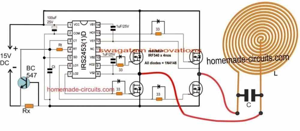
The following figure show s standard induction heater design which can be customized as required by the user, as per their individual preferences.
Circuit Diagram
Circuit Operation
The entire circuit is configured around the popular full-bridge IC IRS2453 which indeed makes designing full bridge inverters extremely easy and foolproof. Here we use this IC for making a DC to DC induction heater inverter circuit.
As can be seen in the design the IC employs nothing more than 4 N-channel mosfets for implementing the full bridge inverter topology, additionally the IC involves an in-built oscillator and a bootstrapping network ensuring an extremely compact design for the inverter circuit.
The oscillator frequency can be adjusted by altering the Ct, and Rt components.
The mosfet H-bridge is loaded by the LC tank circuit using a bifilar coil which forms the induction work coil along with a few parallel capacitors.
The IC also incorporates a shutdown pinout which can be exploited for shutting down the IC and the entire circuit in case of catastrophic circumstances.
Here we have employed a current limiter network using BC547 transistor and configured it with the SD pin of the IC for ensuring a current controlled safe implementation of the circuit. With this arrangement in place, the user can freely experiment with the circuit without the fear of burning the power devices during the various optimization operations.
As discussed in one of the earlier articles, optimizing the resonance of the work coil becomes the key point for any induction heater circuit, and here too we make sure that the frequency is accurately tweaked in order to enable the most favorable resonance for our induction heater LC circuit.
It doesn't matter whether the work coil is in the shape of a spiral bifilar coil or a cylindrical coiled winding, as long as the resonance is correctly matched the result can be expected to be be optimal from the selected design.
How to Calculate the Resonance Frequency
The resonance frequency for the LC tank circuit can be calculated through the formula:
F = 1 / 2π x √LC Where F is the frequency, L is the inductance of the coil (with magnetic load inserted), and C is Capacitor connected parallel to the coil. Make sure to put the value of L in Henry and C in Farad. Alternatively you can also use this resonance calculator software for determining the values of the various parameters in the design.
The value of F can be selected arbitrarily, say for example we can assume it to be 50kHz, L can then be identified by measuring the inductance of the work coil, and finally the value of C can be found using the formula above, or the referred calculator software.
While measuring the inductance L make sure to keep the ferromagnetic load attached with the work coil, with the capacitors disconnected.
Selecting the Capacitor
Since a significant amount of current could be involved with the proposed induction heater for the lab works or for melting ornaments, the capacitor needs to be rated appropriately for the high current frequency.
To tackle this we may have to employ many numbers of capacitors in parallel, and make sure that the final value of the parallel combination is equal to the calculated value. For example if the calculated value is 0.1uF, and if you have decided to use 10 capacitors in parallel, then the value of each capacitor would need to be around 0.01uF, and so on.
Selecting the Current Limiter Resistor Rx
Rx can be simply calculated by using the formula:
Rx = 0.7/Max Current
Here, the max current refers to maximum current that may be permissible for the work coil or the load without damaging the mosfets and for optimal heating the load.
For example, if the optimal load heating current is determined to be 10 amps, then Rx could be calculated and dimensioned for restricting anything above this current, and the mosfets must be selected to handle in excess of 15 amps.
All these might require some experimentation, and Rx can be initially kept higher and then gradually lowered until the right efficiency is achieved.
Cooling the Work Coil.
The work coil can be built using a hollow brass tube, or a copper tube, and cooled by pumping tap water through it, or alternatively a cooling fan can be employed just below the coil for sucking out the heat from the coil from the reverse end of the enclosure. Other suitable methods can also be tried by the user.
Power Supply
The power supply unit required for the above explained induction heater for labs and shops can be built using a 20 amp, 12V transformer and by rectifying the output using a 30 amp bridge rectifier and a 10,000uF/35V capacitor.
Transformerless power supply can be unsuitable for an induction heater since that would require a 20 amp smps circuit which could be extremely costly.


Discussion & Solutions
sir i am happy to bump into this wonderful site. my name is segun jokojeje i work at olatundeprestige limited. at my working place, we deal with furniture, i mean we manufacture chairs using furniture. now i am been employed as researcher. i am being told to research on "HOW TO BUILD HIGH FREQUENCY HEAT GENERATOR OF ABOUT 20KW USING THE PRINCIPLE OF INDUCTION COIL" pls sir i need your assistance
Thanks Joko, You are most welcome!
You can apply the concept which is explained above for your application also, the main parameter responsible for an efficient induction is the resonance level of the LC circuit, which must be correctly optimized.
Please feel free to comment here if you have any further doubts.
pls sir can you explain the main parameter responsible for an efficient induction in the resonance level of the LC circuit and how do i adopt it with the concept above? thank you sir.
It's already explained thoroughly in the above article and in the hyperlinked articles, please go through them carefully…
pls sir can you assist me on how to download proteus software online
oyeledun, I normally do not use on artificial softwares, instead I rely on my brain simulation and practical verification for creating new designs….therefore I am sorry I won't be able to help you much with software simulation
you can download it from here
http://www.mediafire.com/file/xjxpbze64htdeac/Proteus+v8.1+SP1+Pro.rar
thank you sir. but can you shed more light on ct, Rt and Rx
sir how do i come about the Rx Ct and Rt. pls help me sir
please go through the article and the various links
the Rt/Ct is provided in the following article:
https://www.homemade-circuits.com/2014/01/simplest-full-bridge-inverter-circuit.html
Rx formula is also given in the article.
sir do you have article on inverter welding machine and if yes pls i have two welding machines 'schwarze 1080 model' they both power on but are not welding pls sir how do i troubleshoot them?
you can try any square wave inverter circuit rated at a wattage higher than your welding machine wattage.
sir i need you to send me your email. i want to send you a circuit diagram for elaborate explanation
I am working on a project which needs me to switch off the safety mechanism, which shows an error every time the utensil is lifted from the top. I would like to know what mechanism is used to apply this feature in commercially bought heaters and is there anyway around it.Looking forward to your reply. Thank you.
you can do it by enclosing small magnet and a reed switch in such a way that the magnet lies over the reed relay and keeps the reed always activated.
but the moment the ferrous utensil is placed, the magnet moves upwards towards the utensil and sticks to the roof of its enclosure…this moves the magnet away from the reed relay enabling it to get deactivated.
the reed relay can be appropriately configured for the intended cut off.
Dear Saeed,
I am so glad you could ultimately succeed with it.
I will try to give you a perfect solution, and help you to eliminate the bulb in seres
but for this you will have to do a couple of favors to me. 1) Please post this answer under the exact article which you have accomplished. 2) Provide a video clip of your experiment and send it to my email, so that I can use it in my article and share your success story with the world.
I hope you will not mind doing the two things 🙂
Dear Swagatam:
here i should say the page in which you have introduced the induction heater with 4 IGBTs( https://www.homemade-circuits.com/induction-heater-circuit-using-igbt/) will not give me the link(Reply) under which i could post you my questions. but this page does prepare us the link. please fix it so that we could contact with you through the same page. and concerning your second request, OK I will certainly and happily do it by shooting a short film and posting it to you as soon as possible.
thanks a lot for all your kind helps
Saeed Mahdavi
Dear Saeed, I am sorry I was not aware that the comment box was accidentally closed in the IGBT article, I have enabled it now, please post it now, this will allow the visitors to know about your successful experiment.
And I will surely wait for your short video clip which I can post in the same article for the benefit of the readers.
Welcome
Merhaba bayım
İndüksiyon ısıtıcı devresi nasıl tasarlanır sunumunda R1 ve Ct nin değerleri ne olmalıdır.
Teşekkür ederim Saygılar
Merhaba Fm, bunu henüz yapmadım, bu yüzden tam değerleri bilmiyorum. Parça değerlerinin verilen formül ve bazı deneme yanılma yoluyla hesaplanması gerekecektir.
dear.swag/i am iranian and very not domenstrate to english but know fully translate to persian and very tank you for share your train i love you
Thank you dear Hosein, please feel free to ask anything related to electronics through translation… I’ll be most happy to help!
Hi swagatam, is there a way to measure or estimate the power of the heater, only by looking at the values of its components (voltage, inductance, etc)?
Hi Fabinho, you can estimate by looking at the coil element thickness, and the power rating of the mosfets, these two elements can provide a rough idea regarding the power output of the heater.
Hmmm, and how exactly is that? Because for me we should pick a mosfet according to the desired power, right?
Yes that’s right! The ID and VDS of the mosfet should be more than the expected power wattage output.
Thanks already for answering me. So how can I know the expected power output to pick the right mosfet? Here you say: “the max current refers to maximum current that may be permissible for the work coil or the load without damaging the mosfets and for optimal heating the load” is there a way to relate this maximum current to the power? Or I simply look for a mosfet that handles this current and see its power specification?
From the datasheet of the MOSFET, check the ID (drain current) and VDS (drain-to-source voltage) quantities, and multiply them together to get the maximum tolerable wattage of the device, provided it is mounted over a recommended heatsink. These must match your circuit’s V and I levels.
Ok, so just to make it clear, if i’m switching the coil over a 15 DC voltage source, and I limit the current to say 20 amps, I should expect a power output of around 300 W? I should then pick mosfets that handle these voltage and current specifications. The switching frequency does not influence (much) in the power output?
Yes, the mosfet VDS could be around 30V and current ID at 30 amps for the mentioned specs. MOSFETs are normally rated with high switching frequencies so that won’t be a problem.
Ok, thanks for the attention!
Namaskar.
Can you please give me an assembled inducution heating circuit that can work on 12V or 24V battery supply.
Hello, you can easily buy it online from amazon
Hi Swagatam, I am working on Pellet 3D printing, and 12v/24v DC Induction Coil Heating is very attractive and interesting, my project requires Max of 350° C heat but the temperature varies in different locations on a Steel, Aluminium, or Copper pipes, (have not decided which material to use yet) my question is how to control the temperature using either Thermocouple type K (I got one that’s why I mentioned it) or Thermistors (got some them too) as sensors, would you be able to help me please, just the controller part, the rest is easy to get hold of on Internet.
Many thanks in advance, and my E-mail is : siafix@free.fr
Many thanks again.
Siamak
Hi Siamak, I think a thermocouple based design will be good for your requirement. You can try the last circuit explained in the following datasheet:
https://www.analog.com/media/en/technical-documentation/data-sheets/ad8494_8495_8496_8497.pdf
The output will need to be configured with a comparator so that a relay driver stage could be toggled for switching the induction heater ON/OFf.
Good afternoon Swagatam,
Thansk for your prompt answer, I really appreciate your input, I will certainly look into that and see what I can understand from it sicne I am not at all in electronics, I am retired mechanical engineer so …
Cheers and many thanks again.
Siamak
Hi Again Swagatam,
What is really controlling the temperature in the induction heater coil, is it the Frequency or the input voltage, I really not in it all, I need may be a little tutorials to understand the whole thing the Induction Heater coil I understand how it works, well roughly, but how to control the temperature of the tube inside the coil is a mastery to me.
Thanks again.
Siamak
Hi siamak, the temperature can be controlled by controlling the supply current. So if you use a power supply with a variable current facility, you can use it for adjusting the induction heater output as desired. Voltage variation can be also be tried for controlling the output temperature.
A basic induction heater concept is explained in the below article, which uses the ZVS technology which is supposed to be the most efficient.
2 Simple Induction Heater Circuits – Hot Plate Cookers
Thansk you very, very much now I understand a bit better, the rest is calibrating the Thermocouple to get right temperature, great.
Thanks again, you are a STAR.
Siamak
You are most welcome, keep up the good work
Hi Swagatam,
I have just been looking at one of your power supply tutorials and I must say it is really easy to follow, for a non electronic guy I almost understood it and will follow the instructions to try to build one, you don’t have the circuit board lying around by any chance? I will be more than happy to buy it from you, the one with the Transistor 2N3055 that has adjustable Voltage and Current.
Many, many thanks again.
Cheers
Siamak
Thank you Siamak, I undersatnd your concern, however I do not sell assembled items through this website, so I won’t be able to help you with your request, although i truly wish I could.
Hi Swagatam,
No Problem, I understand, is there any other site that you would recommend please.
Cheers
Siamak
Hi Siamak, I do not know about any other site, but you can probably search for ready-made DC power supply modules from amazon eBay etc.
Thank you Swagatam, I really appreciate your input and as soon as my prototype is ready will give you a buzz.
Cheers and thanks again.
Siamak
No Problem Siamak, wish you all the best, please keep up the good work!
Hi Swagatam, I have got hold of many items in order to fulfill the project I have in mind, one of them is induction cooker, my question is; would it possible to change the coil on induction cooker in order to make it a high temperature furnace or a Kiln to fire Ceramics and a like, (1200° C or 2192 F ) if yes how please, I was thinking using copper pipe to make water flow through it in order to cool the coil, but no idea how many turns, but I know the diameter, 90mm, so would you please guide me in this?
Many thanks in advance.
Siamak
Hi Siamak, making a induction heater can be quite difficult unless you know all the practical details. So it is better to buy a ready made unit which may be quite cheap nowadays. After buying you can check the details, and then may be replicate it for future applications.
Even I do not ahve the necessary details regarding the coil diameters for a kiln application
Hi Swagatam,
Many thanks for you honest reply, really appreciate it.
I will follow your advise and get a 2500W one to see how that may pan out for me.
Cheers
Siamak