• Skip to main content
  • Skip to primary sidebar

Homemade Circuit Projects

Need circuit help? Post them in the comments! I've answered over 50,000!

Blog | Categories | About | Hire Me | Contact | Calculators-online
You are here: Home / IC 4060 Calculator

IC 4060 Calculator

This IC 4060 calculator lets you type R1, R2, and C, and see what frequency IC 4060 will give at each output pin. It is super useful if you want to make timers, blinkers, clocks, flasher or any time delay circuit.

How this 4060 Calculator Works

Takes input values for:

  • Timing Resistor (R1 + R2)
  • Timing Capacitor (C)

Then it Calculates:

  • Oscillator frequency
  • All 4060 output frequencies (Q4 to Q14)

As per the 4060 internal oscillator formula:

f = 1 / (2.3 × Rt × Ct)

Where:

  • Rt = total timing resistance (R1 + R2) in ohms.
  • Ct = timing capacitor in farads.
  • f = base frequency (at pin 7, fed to internal binary counter).
  • Each output divides fosc by a binary power (Q4 = fosc ÷ 16, Q5 = ÷32, ..., Q14 = ÷16384).
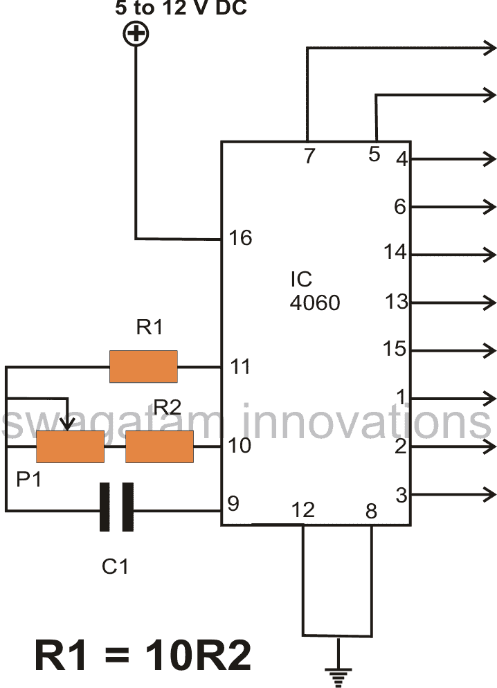
IC4060PinOut
IC4060PinOut

Example:

If suppose we have:

  • R1 = 10k
  • R2 = 10k
  • C = 0.1 µF

Then we may get the following results from the calcuulator:

  • fosc ≈ 217.39 Hz
  • Q4 = ~13.59 Hz
  • Q14 = ~0.0133 Hz (1 pulse every 75 seconds)
IC 4060 Frequency Calculator

IC 4060 Frequency & Time Delay Calculator

Calculator by homemade-circuits.com

How This IC 4060 Calculator Works

here we are using IC 4060, right... that chip has an inbuilt oscillator and a 14-stage binary counter inside. That means it first makes a frequency using an RC network (resistor + capacitor), then it divides that base frequency through a chain of flip-flops and gives it on different output pins.

First, It Needs 3 Timing Parts:

  1. R1 = Resistor connected between pin 10 and pin 9
  2. R2 = Resistor between pin 10 and pin 11
  3. C = Capacitor between pin 9 and ground

We can say that this forms the oscillator tank circuit for the IC. That now sets how fast it pulses internally.

How to Find the Oscillator Frequency:

We use this formula:

f = 1 / (2.3 * Rt * Ct)

Where:

  • Rt = R1 + R2 (total resistance in ohms)
  • Ct = C in farads
  • 2.3 is just a constant that comes from internal logic timing in 4060

So this frequency is made at pin 7, but we do not use it directly, instead it goes inside the IC to the flip-flop counter.

Then What Happens?

The IC then divides that base frequency step by step by 2 every time (like digital binary):

  • Q4 = divide by 16
  • Q5 = divide by 32
  • Q6 = divide by 64
  • Q7 = divide by 128
  • and so on...

That is how we get slower and slower frequencies at each output pin. IC 4060 gives these outputs from Q4 to Q14 so 11 stages in total.

Example Case

Let’s say:

  • R1 = 10k
  • R2 = 10k
  • C = 0.1 µF

Then:

  • Rt = 20k
  • Ct = 0.1 µF = 0.1 * 10⁻⁶ = 1e-7 F
  • f = 1 / (2.3 * 20000 * 1e-7) ≈ 217 Hz

So now inside IC this 217 Hz goes in and gets divided.

You will get:

  • Q4 = 217 / 16 = 13.5 Hz
  • Q5 = 217 / 32 = 6.8 Hz
  • Q14 = 217 / 16384 = 0.0132 Hz = that's like 1 pulse every 75 seconds

So friends now you can see, higher the capacitor or higher the resistance.... then lower the frequency.

Reader Interactions

Questions & Answers

Total Posts: 4
Newest Oldest
Norman D Kelley
June 8, 2026 • 4 months ago #208054

Hi Swagatam,
This 4060 calculator is awesome. Thanks for putting it on the net. I looked for it on your site and did not find it there. You are an awesome engineer!

Reply
SwagatamAdmin
June 8, 2026 • 4 months ago #208065

Hey Norman, thanks very much for your kind words…. glad you found the calculator tool useful.
You can definitely find all these calculators directly from my site….you just have to type the specific calculator name inside the search box of my website, and it will be instantly displayed to you…

Reply
Norman D Kelley
June 18, 2026 • 3 months ago #208497

Hi Swagatam,
I am a little confused. Looking at your oscillator frequency chart, it appears that pin 1, pin 2, and pin 3 should be moved down one step so that pin 1 is Q12, pin 2 is Q13, and pin 3 is Q14. I noticed this when timing outputs on the breadboard. The actual breadboard numbers are not exact but are close. I don’t think Q11 exists. I am only a novice and am not picking at your wonderful post, just letting you know what I experienced.

Reply
SwagatamAdmin
June 18, 2026 • 3 months ago #208503

Hi Norman,
You are absolutely correct, and thanks very much for notifying this typo error in the calculator.
I have now fixed it, please check it and let me know if it works or not…

Reply

Need Help? Please Leave a Comment! We value your input—Kindly keep it relevant to the above topic! Cancel reply

Your email address will not be published. Required fields are marked *

Primary Sidebar

My YouTube Channel

Circuit Simulator: Draw and Simulate Schematics

circuit simulator image


Categories

  • Arduino Projects (95)
  • Audio and Amplifier Projects (134)
  • Automation Projects (18)
  • Automobile Electronics (104)
  • Battery Charger Circuits (90)
  • Datasheets and Components (109)
  • Electronics Theory (151)
  • Energy from Magnets and Earth (43)
  • Games and Sports Projects (11)
  • Grid and 3-Phase (20)
  • Health related Projects (27)
  • Home Electrical Circuits (13)
  • Indicator Circuits (16)
  • Inverter Circuits (98)
  • Lamps and Lights (161)
  • Meters and Testers (72)
  • Mini Projects (28)
  • Motor Controller (68)
  • Oscillator Circuits (30)
  • Pets and Pests (15)
  • Power Supply Circuits (91)
  • Remote Control Circuits (50)
  • Security and Alarm (65)
  • Sensors and Detectors (107)
  • SMPS and Converters (46)
  • Solar Controller Circuits (62)
  • Temperature Controllers (44)
  • Timer and Delay Relay (51)
  • Voltage Control and Protection (44)
  • Water Controller (37)
  • Wireless Circuits (31)


Subscribe to get New Circuits in your Email


Other Links

  • Privacy Policy
  • Cookie Policy
  • Disclaimer
  • Copyright
  • Videos
  • Sitemap

People also Search

555 Circuits | 741 Circuits | LM324 Circuits | LM338 Circuits | 4017 Circuits | Ultrasonic Projects | SMPS Projects | Christmas Projects | MOSFETs | Radio Circuits | Laser Circuits | PIR Projects |


Recent Comments

  • Swagatam on Simple Capacitive Discharge Ignition (CDI) Circuit
  • Swagatam on Remote Controlled Toy Car using 433 MHz Remote Modules
  • James M on Simple Capacitive Discharge Ignition (CDI) Circuit
  • Uchechukwu on Remote Controlled Toy Car using 433 MHz Remote Modules
  • Swagatam on How to Connect IC 4066 in a Circuit

Social Profiles

  • Twitter
  • YouTube
  • Instagram
  • Pinterest
  • My Facebook-Page
  • Stack Exchange
  • Linkedin

Calculators

  • ZVS Induction Heater + Tank Calculator Tool
  • Zener Diode Calculator
  • Wire Current and Thickness Calculator (Ampacity Calculator)
  • Voltage Divider Calculator
  • Transistor Base Resistor Calculator
  • Transistor Astable Multivibrator Calculator
  • TL431 Calculator
  • Solar Panel, Inverter, Battery Calculator
  • Ferrite Core Air Gap Calculator Tool
  • Parallel MOSFET Calculator Tool: How to Connect MOSFETs in Parallel Safely
  • LC Resonance Calculator for EV Battery Charger Circuits
  • LED String Series Resistor Calculator
  • PFC (Power Factor Correction) Calculator Tool: 3kW
  • Passive Power Factor Correction (PFC) Calculator
  • LM567 IC Calculator Tool
  • SMPS Flyback Boost Converter Calculator
  • Shunt Resistor Calculator for Ammeters
  • SCR and Triac Gate Resistor Calculator
  • Battery Back up Time Calculator
  • Boost Converter Calculator (Non-Isolated)
  • Bootstrap Capacitor Calculator
  • Buck Converter Calculator
  • Buck-Boost Converter Calculator
  • Capacitance Reactance Calculator
  • DCM Flyback Transformer & Wire Gauge Wire Size Calculator Tool
  • Filter Capacitor Calculator
  • IC 4047 Calculator (Frequency and PWM)
  • IC 4060 Calculator
  • IC 555 Astable Calculator
  • IC 555 Monostable Calculator
  • IC SG3525, SG3524 Calculator
  • Inductance Calculator
  • Induction Heater Inductor and Resonant Frequency Calculator
  • Induction Heater Work Coil Calculator
  • Inverter LC Filter Calculator
  • LC Resonance Calculator
  • LED Current Calculator
  • LM317, LM338, LM396 Calculator
  • NAND/NOT Gate RC Values Calculator
  • NOT, NAND Gate Frequency Calculator
  • Notch Filter Calculator Tool
  • Ohm’s Law Calculator
  • Phase Angle Phase Shift Calculator
  • Power Factor (PF) Calculator
  • RC Filter Calculator
  • Reactance Calculator
  • Sine Table Calculator for SPWM Arduino Code
  • Small Signal Transistor(BJT) and Diode Quick Datasheet
  • SMPS Calculator for Toroidal Ferrite Transformers
  • SMPS Flyback Transformer Calculator – Design by Target Duty Cycle
  • TL431 Calculator
  • Op-Amp Hysteresis Resistor Calculator

© 2026 · Swagatam Innovations