In this post I have explained a simple mains to generator automatic transfer switch (ATS) which features an initial petrol start which switches to an LPG gas supply via fuel valve changeover switches. The idea was requested by Mr. Junaid.
Technical Specifications
sir i want to make my generator automatic start on petrol then shift the generator on gas and finally turn on the load and when main supply comes it will auto shift the load to main and turn off the generator..
in short i want to use this circuit with automatic ATS for my generator which is placed on 2nd floor. i will very thankful to you if you upload the circuit diagram as soon as possible
my generator is already button/self start.i think that relay will do the job (automatic start) but my main purpose is that the generator should start on petrol then after 10 to 15 second automatic shift it to the GAS/LPG..hope you will help me for this.
Parts List
- R1, R2, R3, R4, R5 = 10K
- C1 = 470uF/25V
- T1, T2 = BC557
- T3, T4 = BC547
- ALL DIODES = 1N4007
- RL1---RL3 = 12V/400 ohms
- RL4 = 12V DPDT, 30amp
The Design
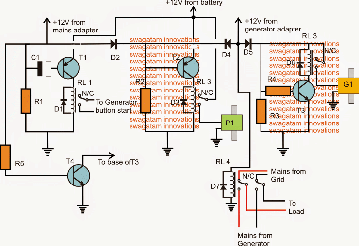
As per the request, the above shown circuit may be incorporated for implementing the proposed generator automatic transfer or changeover relay circuit from petrol to gas using 12V solenoid valves.
The circuit employs a couple of 2-way normally closed solenoid fuel valves for changing over from petrol to gas fuel.
The circuit may be understood with the help of the following explanation:
As soon as mains grid electricity fails, T1 base gets enabled through R1 and C1 and it triggers the RL1 to initiate the connected generator.
RL1 holds on for a few seconds depending the values of R1 and C1 and then deactivates, once this happen the generator can be assumed to have started.
While the above is carried out, simultaneously T2 also switches ON activating RL2 and opening P1 which is a 2-way fuel solenoid valve connected with the petrol tank. Petrol is now allowed to pass to the generator ignition chamber. T2/P1 operates using a chargeable battery supply.
The generator thus is initiated using the petrol from this valve P1 at the onset.
Once the generator starts a 12V adapter connected with the generator output switches ON and sends a 12V supply to the bases of T2 and T3 via D4/D5. This action forces T2 to deactivate shutting of R2 and closing P1 petrol supply...while at the same time T3 switches ON opening G1 gas supply valve by the activation of RL3.
The above execution switches the generator operation from petrol to gas (LPG or CNG)
RL4 makes sure that the load or the appliances are appropriately and automatically transferred from the grid mains to generator mains and vice versa whenever grid mains fails or restores.
In an event when the grid mains returns, T4 disables T3, RL3 and the gas supply to the generator, forcing it to shut off. The entire system now returns to the original mode and the load begins operating via the grid mains AC.
Improved Version
An improved or an upgraded version of the above ATS can be witnessed in the following sections:
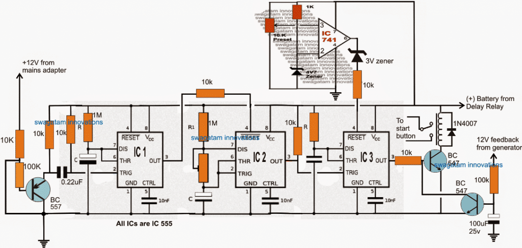
The above diagram shows the "smart" generator starter circuit, which cranks the generator a few number of times and then shuts off. The shutting off is dependent on three conditions:
1) The generator actuates,
2) The stipulated number of cranking is completed without results, 3) The battery is detected to be low.
IC1 and IC3 are configured as monstables, where IC1 is selected to generate a 1 minute high at its pin#3 when AC mains fails, while IC3 is assigned for generating the cranking sequences for 4 or 5 times with 5 seconds period for each cranking.
The center IC2 is rigged as an astable which supplies the cranking triggers to the IC3.
The IC2 preset must be set such that pin3 of IC 2 generates a duty cycle of 20 seconds ON and 2 seconds OFF.
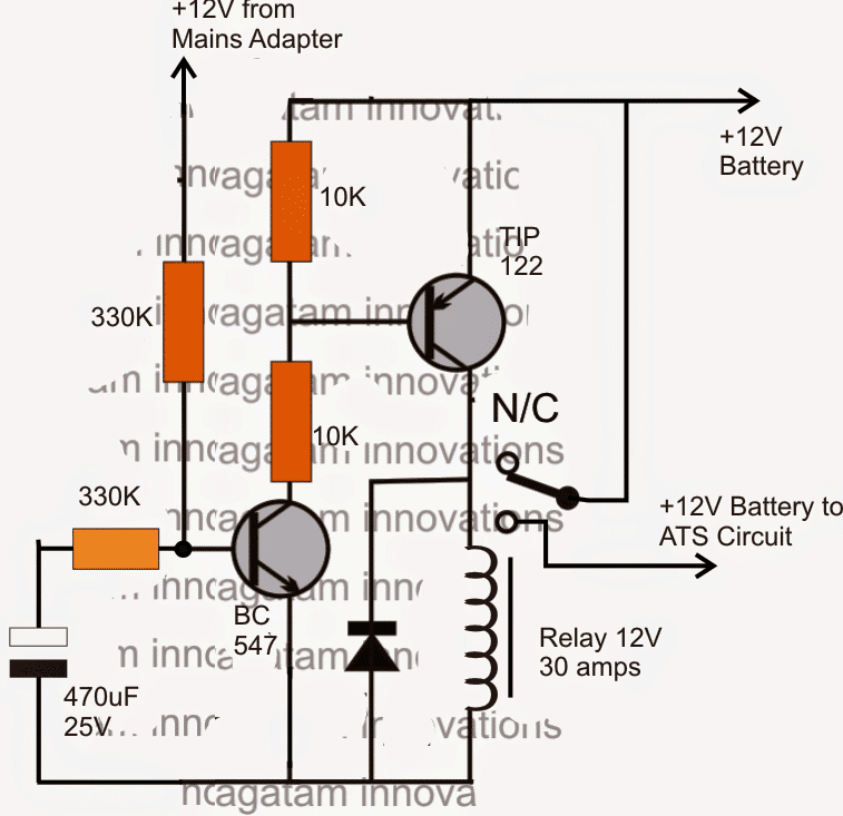
In order to ensure a delayed start ON or a delayed switch OFF the following delay relay circuit may be employed with the above design.


Questions & Answers
Hello sir,
I need a timer relay circuit of 3hrs and that can be varied from 1hr to 10hrs.
Is it possible sir?
Please with explanations.
Best regards.
Jerry.
Hello Jerry, you can get any desired time range by employing the following concept:
https://www.homemade-circuits.com/how-to-make-long-duration-timer-circuit/
Hello sir,
‘I’m very grateful for your prompt response. I really appreciate your kind gesture.
It’s my pleasure Jerry!
Hello sir,
I have sent the internal diagram of the contactor to you. Did you receive it?
Hello Jerry,
No I did not receive it?
Hello Jerry, is your contactor operation same as relay? According to me contactors use built-in start/stop switches, so it can be complicated to work with contactors
Hello sir,
The contactor operation is same as relay just that the contactor doesn’t have the ‘NC’ terminal. It has two terminals for the coil and 2,3,or 4 poles depending on your choice. On one side of the poles is where you connect your supply while on the opposite side is where you connect your load. When the coil is powered, the contact closes thereby allowing flow of signal from one side of the pole to the other.
Please sir, is the email i used working? so that i can send more pictures to you.
Hello Jerry, I have seen the picture, but it didn’t help. I wanted the internal diagram of the contactor so that I can understand the terminals. If you have the terminal diagram you can send it to the same email.
Hello sir,
I think I sent the contactor picture to your e mail.
Hello Jerry, the obstruction light that you had requested has been published here:
https://www.homemade-circuits.com/led-obstruction-light-circuit/
Hello sir.
From what I propose to do, I want to use two 3 pole 230VAC 30A contactors which will have a mechanical interlock inbetween, what I want you to do for me is to design a circuit that will start a generator when there is power failure from national grid and stop it when the power is back with delay cct like you have in other designs that I’ve seen but instead of the relays which you used, I will choose to use contactors that have no ‘common’ or ‘NC’ points though a relay will be employed to stop the generator but not to transmit power. The coils of the contactors will only work with the voltages from the grid and the generator except if I will use dc contactors say 12VDC or 24VDC. I hope you got my point. Thanks.
Without actually seeing how a contactor needs to be wired it can be difficult to design the circuit!!
Hello sir,
Thanks for your response. Meanwhile, I’m yet to see the inclusion of the contactors in the design
Hello Jerry, can you please show me a sample pic of a contactor unit, I guess it works with start/stop switches, right?
Hello sir,
I’m Jerry, I’ve gone through some of your works and was pleased with the wonderful works and lecture you give online. I appreciate your kind gesture.
I have a request to make sir, I need an ATS circuit that will start a generator when the mains is out and will also stop it when mains is restored. In my own case, I will be using contactors instead of relays for the changeover(230VAC). I will also need a solenoid valve that will turn off the fuel line. kindly assist me . Thanks
Thank you Jerry, I am glad you are liking my posts, do keep visiting!
I have a couple of designs relevant to your request, can you please check the following link, whether these suit your application or not:
https://www.homemade-circuits.com/automatic-transfer-switch-ats-circuit/
For the contactors I may have to add some more modifications to the existing relay stages.
Hi sir
Really you are great very valuable information.
Sir i have a doubt two years back i was searching for feul saving device in online that time i found a device it is HHO milage kit which runs in water i didn't trust it but nowadays its getting popular and lot of devices available in online marketers. Can you please tell me about this pls.
Thank you Naresh,
I have a post in my blog related to your query, you can check it out here:
https://www.homemade-circuits.com/2015/05/how-to-use-hho-fuel-cell-in-automobiles.html
Sir thanx for updating improved version and yes after reading some safety issues i change my mind.(sorry for that)..thanx for helping me
My pleasure, Junaid!
Hi Swagatam
Mr. Junaid's statement "my generator is already button/self start.i think that relay will do the job (automatic start)" indicates that he want to replace the button with a relay.
I agree that he has mentioned to use this circuit with ATS but the question is what actually this circuit is suppose to do? The circuit is no doubt an ATS itself!
Ah yes, I would advise you to include all the features to make the ATS as smart as you are…… 🙂
I have worked on your T1 network but could not make it work so I would recommend monostable 555 as an alternate.
Hi Abu-Hass,
Mr.Junaid has changed his status, may be after seeing so many features he is now interested to build a more advanced one.
The issue you are presenting is a secondary issue, and it can be corrected simply by adding a resistor across base of T1 and the positive line, it's does not look so difficult.
actually the cap could have discharged even without the above aid if the emitter was connected on the same positive line
I have updated the smart version, you can check it out.
Hi Swagatam
Junaid has already clarified the situation. And yes, a voltage monitor would be an additional feature.
Regarding the T1 network, following is the behavior of the configuration:
a) Initially MAINS=ON, the Cap C1 is not charged >>> Nothing happens — (OK)
b) When MAINS=OFF, the Cap C1 gets charged thru voltage from emitter >>> The engine cranks until C1 is charged — (OK)
c) When MAINS=returns ON, the Cap C1 is remain in charged status >>> Nothing happens — (OK)
d) When MAINS=OFF, C1 is already charged >>> The engine does not cranks —- (OOPS!)
Solution:
In step (c) when the Mains is restored, C1 should be discharged. And its discharging is quite complicated task in this configuration.
Hi Abu Hafss,
As per the request, it seems the circuit is required to handle the fuel section of the generator only, the main intention appears to be the fuel changeover here.
In my "smart" cranking circuit I'll include the 555 monostable along with a battery voltage monitor which will make sure that the cranking never happens if the battery voltage is dragged below a certain acceptable threshold,
Hi Swagatam
Firstly, RL1 pins should be such connected that when the grid mains is available, the engine's starter motor is disconnected from the battery +12V. When grid mains goes off, the RL1 is to get de-energized and hence the starter motor is connected to +12V battery thru NC pin.
Secondly, please check the T1 network. I doubt that C1 would ever get charged or RL1 would ever get energized.
Besides, the design needs some additional safety circuitry:
a) T1 should crank the generator's engine for a time determined by R1 & C1. Suppose this time is 5 seconds. What happens if the engine starts at 2sec? The starter motor will continue to crank until the 5 sec are completed……… This should be avoided!
b) What happens if the engine does not starts even after 5 sec of cranking? The cranking should resume after 5 sec delay.
c) There must be some grace time to deal with power surges. Sometime because of surge the grid supply is disconnected momentarily and then it is restored. To tackle this, the generator should be cranked after some delay like 5-10 sec.
d) Similarly, when the grid mains returns, the load should be shifted to the grid mains but the generator should get switched off after some delay like 5-10 sec.
OK Junaid, if you don't have it (on the 2nd floor) 🙂 then I'll consider and try to upgrade the circuit.
Hi Abu Hafss,
The sentences are contradicting, because I believe an ATS has a generator start capability built-in.
If your T1 stage is not working then you should check why it is not working, probably you can connect an LED in series with the base or in parallel with the relay…the relay coil should not have a low resistance (not less than 300 ohms) if it has then the capacitor value will need to be proportionately increased.
I have already verified this configuration in my earlier set up, although I had used NPN transistor there.
However in the enhanced version (in case I produce it) this stage will be eliminated anyway.
hi Sir thanks for uploading the circuit..i did not have a ATS right now i am working on it..if possible kindly include "Abu-Hafss" suggestion in above circuit so i may be made my ATS more smarter.
HI Swagatam
In his request, Mr. Junaid mentioned "my generator is already button/self start.i think that relay will do the job (automatic start)" which indicates that he intends to replace the button with relay which would crank the engine.
I agree that Mr. Junaid has mentioned "to use this circuit with automatic ATS" but, on the other hand he is asking for a circuit which will do the job of an ATS……..so as far as I understand, he needs a completely independent ATS circuit. Here, I would like Mr. Junaid to clarify his requirement.
Yes, you should include all the features to make an ATS which is as smart as you are….. 🙂
I have checked the T1 network and could not make it work. Yes a 555 would be more reliable alternate.
…from the request details it seems Mr. Junaid already has a full-fledged ATS he only wanted the petrol/gas changeover circuit stage, so that he could attach it with the existing ATS
Hi Abu-Hafss,
Thanks for the useful suggestions!
However, as mentioned in the request the generator is supposed to be a button start type, which only needs the button to be pressed for a few seconds, that's why I did not consider any other criticality.
Moreover, in the request more emphasis is given on the petrol to gas changeover operation and that's another reason why I did not concentrate on the cranking complexities, however if anybody needs the cranking timing feature to be included they may associate the above circuit with the one that's explained here:
https://www.homemade-circuits.com/2013/11/automatic-transfer-switch-ats-circuit.html
The mains fluctuations can be an issue and may be tackled by adding a delay ON timer as explained here:
https://www.homemade-circuits.com/2013/11/automatic-transfer-switch-ats-circuit.html
Your point d) is also right, if possible I'll try to include all these in the above circuit…. and also try to improve the cranking stage and try to make it "smarter"
The T1 configuration is correct according to me and it will keep RL1 ON for a few seconds depending upon the values of C1/T1, you can try it yourself….however if T1 is too large, RL1 will not respond, and if if C1 is too small RL1 will switch OFF quickly…so these two parts will need to be correctly balanced for getting an optimal ON time.
Alternatively one may also try a IC 555 monostable for the same.