The electric fence charger circuit presented here is basically a high voltage pulse generator. The super high voltage is derived from a commonly used automobile ignition coil.
An astable multivibrator is used to generate the required frequency to drive the ignition coil. Another astable is used to control the pulses supplied to the fence.
Audio/Video Representation
Protecting Crops with Fence Charger
If you have large agricultural fields and desperately need to protect the crops from uninvited guests like animals and possibly humans, then this electric fence charger device is just what you are looking for. Build and install it yourself.
An electric fence is an electrified high voltage barrier which produces painful shocks if physically touched or manipulated.
Thus such fencing basically function as deterrents for animals as well as human intruders and stop them from crossing the restricted boundary.
The present circuit of an electric fence charger is designed and tested by me and has proved sufficiently powerful for the application.
20 kV from the Sparks
The fence charger circuit is able to produce voltage pulses up to 20,000 volts, needless to say about the fatality rate involved with it.
However the pulses being intermittent, provides the subject with enough time to realize, recover and eject.
The generated pulse is so powerful that it can easily arc and fly-off between short distances of around a cm. so the fencing conductor needs to be separated adequately to avoid leakages through arcing and sparking. If not tackled, may drastically reduce the effectiveness of the unit.
Here the generation of high voltage is primarily carried out by an automobile ignition coil.
The winding ratios of an ignition coil are specifically designed and intended for creating high voltage arc between a two closely spaced conductors inside the ignition chamber to initiate the ignition process in vehicles.
Basically it’s just a step-up transformer, which is able to step-up an input applied voltage at its primary winding to monstrous levels at its output or the secondary winding.
Warning: Please be careful when handling the following fence charger circuits while powered, as several parts and the ignition coil generate very high voltages. Touching the high-voltage output can result in a severe, painful shock and potential injury. Always take basic safety precautions when testing, as the author assumes no liability for accidents or injuries.
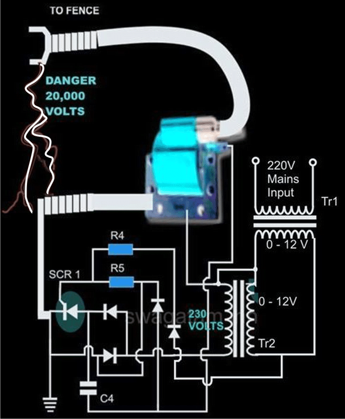
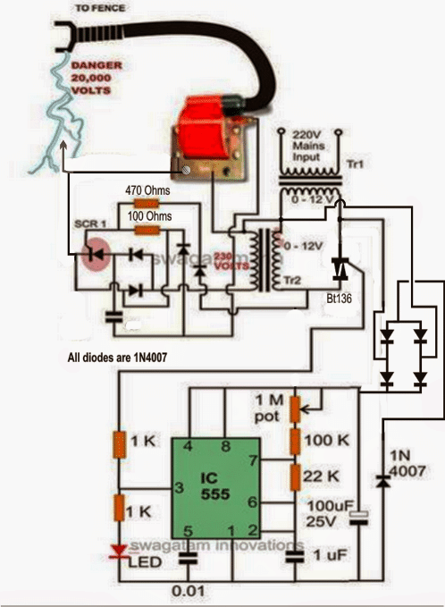
Let’s diagnose the proposed electric fence charger circuit more deeply.
Circuit Operation
In the CIRCUIT DIAGRAM we see that the entire circuit is basically comprised of four stages.
A DC oscillator stage,
An intermediate 12 to 230 volts step-up stage,
The voltage collector and firing stage and the super high voltage-booster stage.
TR1 and TR2 are two normal step-down transformers whose secondary windings are connected through SCR2. TR1 input primary winding may be selected as per the country specification.
However, TR2 primary should be rated at 230 volts.
IC 555 along with the associated components forms a normal astable multivibrator stage. The supply voltage to the circuit is derived from the secondary of TR1 itself.
The output from the astable is used to trigger the triac BT136 and the whole system, at a particular fixed intermittent rate as per the settings of P1.
During the ON periods, the triac connects the 12 volt AC from TR1 to the secondary of TR2 so that a 230 volt potential instantly becomes available at the other end of TR2.
This voltage is fed to the voltage-firing stage consisting of the SCR1 as the main active component along with a few diodes, resistor and the capacitor C4.
The fired voltage from SCR1 is dumped into the primary winding of the ignition coil, where it is instantly pulled to a massive 20,000 volts at its secondary winding. This voltage may be suitably terminated into the fencing.
The high voltage generated by this electric fence charger will need to be carefully applied across the whole length of the fence.
The two poles from the ignition coil connected to the fence wiring should be kept at least 2 inches apart.
The pillars of the fence should be ideally made of plastic or similar non conducting material, never use metal and not even wood (wood tend to absorb moisture and may give path to leakages).
Parts List for the explained electric fence charger circuit using SCR
- R4 = 1K, 1WATT = 1
- R5 = 100 OHMS, 1WATT = 1
- P1 = 27K PRESET = 1
- C4 = 105/400V PPC = 1
- ALL DIODES ARE 1N4007
- IC = 555 = 1
- TR1 = 0-12V/3Amp (120 or 230V) = 1
- TR2 = 0-12V/1Amp (120 or 230V) = 1
- THE SCR IS BT151 = 1
- THE TRIAC COULD BE ANY 1AMP/400V SUCH AS BT136 = 1
- TWO WHEELER IGNITION COIL SHOWN IN BLUE/RED COLOR = 1
The above concept can be also implemented using a BJT for the generating the triggering pulses for the transformer, as shown below
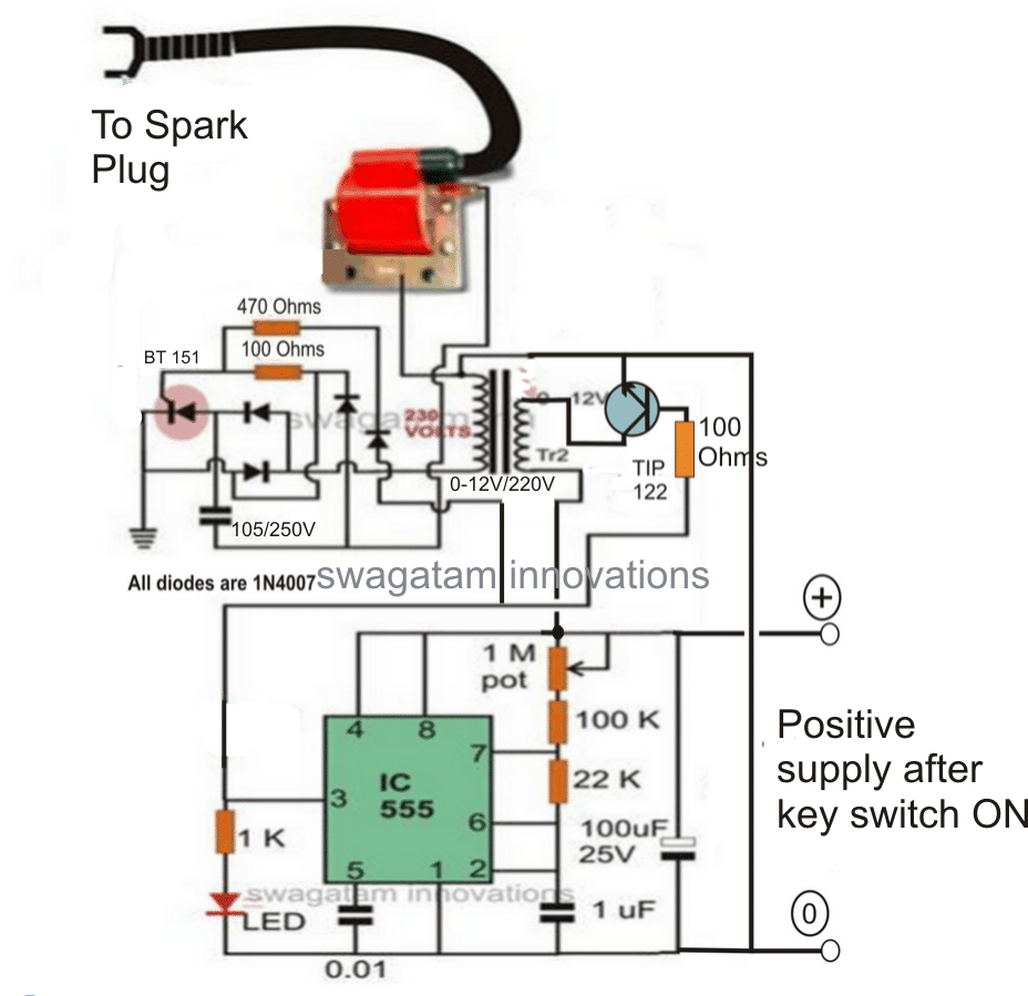
Please increase the TIP122 base resistor value to 10K for reducing increased dissipation from the transistor.
Adjust the 1M pot such the ON time of the IC 555 is much shorter than the OFF time, for reducing current consumption.
Video showing how an Ignition Coil could be applied for producing high voltage
Mini Fence Charger Circuit
The discussed fence charge above is relatively lager and stronger with its specifications. If you need something smaller, then the following mini fence charger circuit can be quite handy.
This may be used for driving away pests like cockroaches, slugs, worms, snails from any desired small premise such a terrace garden, balcony pot plants or simply for guarding food stuffs etc.
Circuit Operation
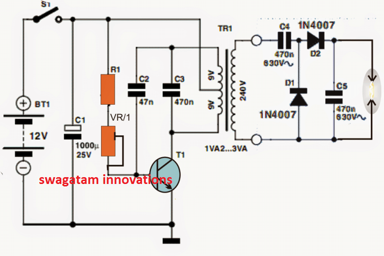
The referred circuit for the mini fence charger is shown below, it may be understood with the help of the following points:
The top part of the transformer winding basically delivers a reinforcement to the base of the transistor by means of C2 the T1 keeps being confined on to the conduction status until C2 charges completely, ending the latch and compelling the transistor to commence the conduction sequence afresh.
R1 that may be a 1K resistor is installed to restrict the base gain for T1 to secure inhibits whereas VR1 that could be a 22k preset could very well be tweaked for acquiring an effectively pulsating T1 rate.
C2 could be additionally fine tuned by attempting supplementary values until the maximum output is accomplished at the trafo output
Transformer Specs
The transformer could possibly be any iron-cored step down transformer (500mA) commonly employed in transformer version AC/DC power supply devices.
The output immediately across the transformer output may be at the evaluated secondary level, for instance whether it is a 220V secondary, in that case the output could possibly be anticipated to be with this levels.
The above degree could possibly be even more heightened or stepped up by means of the connected diode, capacitor charge pump set-up corresponding to cockroft-walton power generator system.
The set-up boosts the 220V level to scores of volts that could be compelled to spark across an accordingly deployed finish terminals of the charge pump circuit.
The above end high tension end terminals could be appropriately wired up across the whole length of the area which needs to be guarded from the bugs and for implementing the intended fencing charging operations.
The fence charger wires must be separated by some minimum distance so that the sparks do no keep flying of even in the absence of any external intrusion from the insects.
The explained mini fence charger circuit concept could be furthermore utilized in mosquito swatter bat purpose by swapping the iron cored transformer with a ferrite core counterpart.
Circuit Diagram
Using 4049 IC
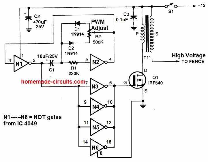
Since the above fence charger can operate with a 12V battery, it is a suitable option for remote locations which may lack an access to AC power.
An oscillator circuit is constructed using two NOT gates N1 and N2 from a 4049 hex-inverting integrated circuit.
It has a PWM control feature using the pot R2. This can be used to fine-tune the output PWM to optimize output voltage and performance of the fence charging.
The MOSFET switches to ground whenever the positive pulse of the input at Q1's gate is available, connecting the primary winding of T1 across the 12 volt source.
When the MOSFET gate signal turns logic low, the current between Q1 and the transformer's primary is inhibited. This causes a high voltage pulse to be produced through T1's secondary winding.
This causes a high voltage in the order of around 20 kv to be generated at the output of T1. This output can be linked with the fence for the intended electrification.
Remember, T1 can be any automobile ignition coil. We recommend using a two-wheeler ignition coil.
How to Setup
- Setting potentiometer R2 to its half way is the easiest technique to optimize output arc and circuit performance.
- Next, hook up a DC current meter in series with the circuit and power supply positive.
- T1's output is then positioned approximately half an inch above the ground line of the circuit.
- Finally, R2 is adjusted for getting optimum output voltage spark and lowest current consumption by the circuit.
Fence charger circuit using SCR and Ignition Coil
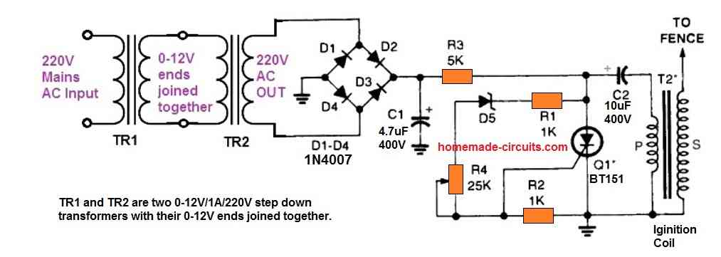
Another simple design of a fence charger circuit is shown in the above figure. This circuit is designed to work with a 220V or a 120V AC input. So, this circuit can be used only in places where an AC outlet is available.
The SCR along with the capacitor C2 forms a capacitive discharge circuit, which works with a 310V DC input.
The 310 V from a 220 V RMS input or a 170 V from a 120 V RMS peak voltage inputs is achieved through two step down transformers connected back to back.
TR1 and TR2 transformers are two 0-12V/1A/220V/120V transformers configured with their 0-12V ends attached together.
This allows the circuit to get a high voltage low current peak DC supply input for the intended capacitive discharge operations.
When AC power is switched ON, the 220V or 120V from TR2 is converted into the required high voltage peak supply via the bridge rectifier and the capacitor C1.
The peak DC passes through R2 and the primary side of the ignition coil until C2 is fully charged. When charged fully it develops sufficient voltage to switch ON the zener diode D5.
D5 now conducts and fires the SCR. The SCR triggers ON and discharges C2 through it. This instantly causes the stored peak DC inside C2 to suddenly pass through the ignition coil primary.
This in turn causes an equivalent high voltage in the order 20 kV to be induced on the secondary side of the ignition coil. This 20 kV generated output is used for electrifying or charging the intended fences.
Simplest Fence Charge using Just a Couple of Transformers
If you have an access to a 220V AC or 120V AC mains input within reach, then perhaps the following simple transformer based AC fence energizer circuit could be used for the purpose, without incorporating any kind of complex circuitry.
The low current 220V side can be used to energize the fence.
To increase the output voltage to 500V AC you can use a 0-6V / 220 V transformer for the right hand side transformer.
Also if you wish to increase the current capacity of the output you can appropriately increase the Ampere rating of the two transformers.

The capacitor may be selected depending on the level of electric shock needed for the application.
Another simple Fence Charger Circuit using Transistors
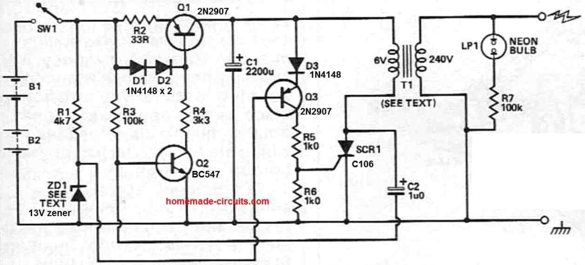
Capacitor C1 undergoes charging via a constant current facilitated by transistor Q1.
Zener diode ZD1 maintains the base of Q3 at 13V, enabling conduction through D3 as the capacitor's charge reaches approximately 14.3V.
The conduction in Q3 delivers the gate trigger to SCR1. Subsequently, C1 discharges through the modified 6V winding in the transformer's primary.
This action generates a high-voltage pulse at the circuit's output, which is linked to the fence.
The discharge of C1 eliminates the gate drive to SCR1, allowing it to turn off as soon as the current reaches zero.
Diode D3 prevents excessive current flow through the base-emitter junction of Q3, safeguarding against reverse breakdown.
The current is limited to the diode's reverse leakage current, ensuring the safety of the transistor.
Under open circuit circumstances, SCR1 turns off independently as the transformer experiences slight ringing, diverting current from Q1 away from SCR1 and towards C1.
However, this automatic turn-off isn't assured when the circuit is loaded. To guarantee reliable turn-off of SCR1, C2 and Q2 temporarily interrupt the current from Q1, providing time for SCR1 to recover.
A resistor and neon bulb combination provides a visual confirmation of the fence charger circuit's operation, eliminating the necessity of touching the output terminals.
The lamp flashes with each pulse of the fence charger, indicating its functioning.
The T1 transformer can be any ordinary step-down transformer, connected in a reverse fashion, so that it steps-up the 6V to a 240V output.



Questions & Answers
the negative terminal is the ground point.
the positive terminal goes to C4.
the central top cap is the high tension terminal.
you may refer to this diagram
static.ddmcdn.com/gif/ignition-system-coil.gif
The capacitor accepts and stores the 220V input, and in the process when the firing limit of the SCr is crossed, the SCR fires and shorts the capacitor leads across the connected winding of the coil discharging the cap voltage into the coil. This discharge is stepped-up by the coil to the specified levels at the high tension output….so this is how it works.
dear sir sir how measure 20,000 v
thanks
it's current that may be lethal, not voltage, it will depend on the transformer current rating.
hai……this circuit is very use full to my home…for wild elephants…please correct diagram send to me..my email address is – madushankagamage445@gmail.com –
a simpler solution is to pulse TR2 directly with the IC555 via a transistor or a mosfet and eliminate TR1 entirely from the CDI circuit.
how can i measure the ampere from tranformer?
connect meter prods directly across the secondary output wires, in the AC Amp range
Hi Swagatam
1) According to the circuit description, the right transfo should be labelled TR2 and the the left one as TR1.
2) What is the purpose of the diode in the lower right corner, next to the capacitor?
3) Is it important to connect one lead of the primary to one lead of the secondary, of the 2nd transformer?
Hi Abu-Hafs,
2)the diode is for grounding the negative spikes.
3) yes it's very important for providing the ground to the scr with reference to its gate voltage.
Hi Swagatam
For my CDI bench test, I want to switch off the traic whenever there is trigger pulse. Please check if following configuration is OK:
I haven't used traic before so please suggest me suitable values for the resistors and how much collector current would be enough to operate BT136?
Hi Abu-Hafss,
It's correct, the resistor can be any value between 2k and 10k as the triac would require just 15mA or even less to trigger fully.
dear sir
i want to make solar fence enegiser. i m from chemical field so don't have technical info.so plz guide me for the same. can we have ready made circuit for energiser?
Dear Ramesh,
I think the following circuit will be perfect for your applications:
https://www.homemade-circuits.com/2012/05/make-this-solar-powered-fence-charger.html
Hy Swagatam
i like your ckt but have some questions
there is some difference in the part list and fig -2 also some parts from fig 1 also differ from fig-2
so which is completely write part list or fig-1 or fig2
thanks
Hi Samaj,
I'll do the necessary corrections soon. thanks
hello sir
any idea about make alarm circuit when fence wire is short.
please give me circuit.
hello vikas, it could be implemented using a current sensor stage…..if possible I'll try to update it in the above article.
sir can y guide me whats the exact purpose of first circuit which make a alternate voltage and how its operate
the first circuit is explained here:
https://www.homemade-circuits.com/2011/12/how-to-make-capacitive-discharge.html
and what is 1M pot is it a variable resistor which adjust the frequency
yes it's for adjusting the 555 IC frequency
hi Swagatam
i made this fence circuit but its working fine for 1 minutes
after 1 minutes traic BT136 getting hot and spark stops
whats cause for that ?
Hi mukpti, you can connect a heatsink with the triac or use a 10ohm/5 watt resistor in series with its supply leads
thanks for reply
now am changing from 230 ac to 12 dc power supply options
for that i am going to replace bt136 with tip122 and 1k resistor with 100 Ohms that connects to tip122 Base
but i not sure with 3 legs of tip122
1st leg of tip122 connect with output from timer 555
2nd leg with TR2 and 3rd with ground wire
is that correct ?
I can specify the leg orientation here, but it would be better if you check it through an image.
just type and search TIP122 datasheet and you'll be able to get the complete info regarding the device, or you can click the "images" option in Google search for getting an instant view of the same
Thanks a lot
i made it working but still tip222 getting hot
it will get hot, you will need to add a heatsink to it…..also try increasing its base resistance from 1K to may be 22k or even higher.
can tip122 replace with MOSFET irfz44 in 12v dc model or BT136 replace with MOSFET irfz44 in AC230 model to solve hitting problem ?
thanks
mosfet cannot be replaced with BT136….it can be replaced with TIP122 in the DC model
thank you
Hi will this work on a colourbond roof? I'm desperate to stop intruders, thank you
the wiring will need to be done as done for fences, if you just connect it to the roof it won't work
can we remove TR2 and use direct 230 ac ?
if removed tr2 and trigger SCr from 555 will work ?
please see this
https://drive.google.com/file/d/0BzbroLfbdv4haE53eWxvc0Vmdk0/view?usp=sharing
In your drawing the SCR will instantly burn, since it's directly connected across the mains…and anyway it looks dangerous.
instead, you can try one of the designs shown in the following article:
https://www.homemade-circuits.com/2013/01/make-this-enhanced-capacitive-discharge.html
Sir, I have read your home made electric fence energizer and found very simple designed and cost effective. So m also planning to design one electric fence energizer with following parameters;
Input 12v DC
Pulse width 100micro secs
Maximum output is 2joules
working length is 200m to 40km.
Therefore can you kindly advice me.
Gom, pulse width can be set by adjusting the 22k resistor value appropriately.
however I am not sure about the joule calculation,, you can probably do it by yourself.
for 40km length you may have to install many such circuits at appropriate intervals for enabling an effective outcome from the units.
Thank you for your reply. Let me try it .
hi swagatam,
Can we use this circuit to energize 4KM ?
Hi Vishwa, yes it looks possible since the voltage is high enough, around 20kV
Sir, since the output voltage we get is in pulse how can we measure output voltage?
Gom, 20kV can be difficult to measure with ordinary DMM….but it's not required…you can judge it visually…if the spark is able to fly across a 1cm gap or more then it's well over 20KV
sir give ur number pls
Hi Swagatam, is there any PCB for both circuits?
Hi Bursach, sorry no ready PCB designs for the circuits
Ok, I will make my own. Can I use for example Myrra transformers to montage to pcb? The second Tr I have is 2×1.25A, is it sufficient or it has to be just 3A?
The transformers are ordinary step-down iron core type since these are supposed to be used with the 50/60Hz from the mains, ferrite versions will not work
I think these are ordinary transformers but compact, check this link, what I mean :
http://www.kelco.rs/katalog/detalji.php?ID=6928
I think these Tr are not ferrite.
yes, these can be used!
Thanks Swagatam, I suppose 2×1.25A= 2.5A for Tr1 with 30VA and 2x12V will be enough ?