In this article I will comprehensively discuss a relatively accurate electronic heart rate sensor circuit processed by a few discretely wired opamp circuit stages, and subsequently we'll learn how this can be modified for making a heart rate monitor alarm circuit.
Using IR Photodiode Sensors
The sensing of the heart pulses is basically done by two IR photo diodes one being the transmitter of IR while the other acceptor.
The IR rays thrown by the transmitter diode is reflected from the finger tip blood content of a person and is received by the receiver diode.
The intensity of the reflected rays vary at a proportion determined by the heart pumping rate and by the difference in the oxygenated blood levels inside the blood content.
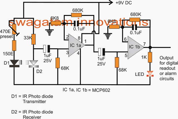
The sensed signals from the infrared diodes is processed by the shown opamp stages which are in fact a couple of identical active low pass filter circuits determined to cut-off at around 2.5 Hz. This implies that the maximum attainable heart rate measurement would be restricted to about 150 bpm.
We use the IC MCP602 for the processing in the form of IC1a and IC1b in the proposed heart rate sensor and processor design. The IC is a dual opamp manufactured by microchip.
Circuit Operation
It's designed to work with single supplies and thus becomes extremely favorable for the discussed circuit which is supposed to operate from a single 9V cell.
This also means that the output of the opamp would be able to produce a full positive to negative voltage swings corresponding to the sensed heart rate signals from the IR diodes.
Since the ambient conditions may be polluted with plenty of stray signals, the opamps needs to be immunized against all such spurious electrical disturbances, therefore blocking capacitors in the form of the shown 1uF capacitors are positioned at the inputs of each opamps.
The first opamp is set to produce a gain of 101, the second one being identical to the first IC1a configuration is also set at 101 gain.
However that implies that the total or the final gain of the circuit at the output is rendered at an impressive 101 x 101 = 10201, such high gain ensures a perfect sensing and processing of the extremely weak and obscure input heart rate pulses delivered from the IR diodes.
An LED can be seen attached across the output of the second IC1b opamp which blinks in response to the received heart rate pulses from the IR diode stage.
The application presented here is for reference design purposes only and is not intended for any life-saving or medical-monitoring use.
Circuit Diagram
How to Set up the Heart rate sensor circuit
Setting up the proposed heart rate sensor, processor is actually very easy.
As we all will understand that the difference between the oxygenated blood and de-oxygenated blood could be hardly distinguishable and require extreme precision in all respects in order to enable the processor to judge the subtle differences within the blood stream and yet be able to convert into a swinging voltage change at the output.
In order to ensure a perfectly optimized IR beams from the IR Tx diode, the current through it must be restricted to a well calculated proportion such that the oxygenated blood offers a relatively higher resistance for the rays to pass through but allows relatively lower amount of resistance for the rays during the deoxygenated state of the blood. This makes it easier for the opamp to distinguish between the beating heart pulses.
This is simply done by adjusting the given 470 ohm preset.
Keep your index finger tip over the D1/D2 pair, switch ON power and keep adjusting the preset until the LED at the output begins to develop a distinct flashing effect.
Seal the preset once this is achieved.
Positioning arrangement of the index finger over the enclosed photo diodes
It may be done by soldering the diodes over the PCB at some calculated distance apart that becomes just good for the index finger tip to cover the radiating tips of diodes completely.
For an optimal response the diodes must be enclosed inside an appropriately sized opaque plastic pipes, as shown in the following figure:

In the following section we'll learn about a simple heart rate monitor and alarm circuit specially designed for the elderly citizens for keeping a track of their heart critical rate.
Here explores a simple circuit which may be used for monitoring the critical heart rate of a patient (senior citizen), the circuit also includes an alarm for indicating the situation. The idea was requested by Mr. Raj Kumar Mukherji
Technical Specifications
Hope you are fine. The purpose of writing here is to share with you an idea of a project - to design a "heart rate monitor alarm" which can be made by using commonly available low cost components and which will produce an audible alarm whenever the pulse rate of anyone is found to be abnormal. It should meet the following conditions as well:a. Compact and light weight, therefore portableb. Consume minimum power, therefore should run 24x7 for a month or two from a couple of AA batteries or a 9 volt packc. Should be fairly accurate in it's performanceI know there are many such circuits available on the net but their performance and reliability are questionable. The unit can be very useful especially for elderly people (with / without a heart disease), for patients who are bed ridden and so on. When the heart either beats at a rate higher/lower than a set average threshold value, the alarm will sound loudly enough to alert people around the patient.I hope that my proposal is clear to you. However, if you have any doubt, please drop me an e-mail.Thank you,Kind regards, Raj Kumar Mukherji
The Design
In the previous post I explained how to make a heart rate sensor circuit with processor, which can be appropriately used in the proposed critical heart rate alarm circuit.
The application presented here is for reference design purposes only and is not intended for any life-saving or medical-monitoring use.
Circuit Diagram
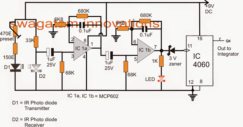
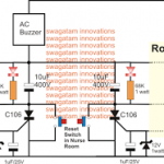
Referring to the diagrams above, we are able to see a couple of circuit stages, the first being the heart rate sensor/processor with an integrated frequency multiplier, while the second in the form of an integrator, comparator.
The upper signal processor design has been comprehensively explained in the previous paragraph, the additional voltage multiplier which is been integrated to the processor uses the IC 4060 for multiplying the relatively slower heart rates into a proportionately varying high frequency rate.
The above proportionately varying high frequency heart pulse rate from pin7 of IC 4060 is fed to the input of an integrator whose job is to convert the digitally varying frequency into a proportionately varying exponential analogue signal.
Finally this analogue voltage is applied to the non inverting input of a Ic 741 comparator. The comparator is set through the attached 10k preset such that the voltage level at pin3 stays just below the reference voltage at pin2 when the heart rate is in the vicinity of the safe region.
However if the heart rate tends to increase over the critical region, a proportionately higher voltage level is developed at pin3 which crosses the pin2 reference level causing the output of the opamp to go high and sound the alarm.
The above set up only monitors and alarms regarding the higher critical heart rate, in order to achieve a two way monitoring, meaning to get an alarm for both higher and lower critical heart rates...the second circuit comprising the IC555 and IC741 could be entirely eliminated and replaced with a standard IC LM567 circuit set to keep its output low at the safe pulse rate, and go high at the up or down critical rates.
The signal conditioning circuit consists of two identical active low pass filters with a cut-off frequency of about 2.5 Hz.
This means the maximum measurable heart rate is about 150 bpm. The operational amplifier IC used in this circuit is MCP602, a dual OpAmp chip from Microchip.
It operates at a single power supply and provides rail-to-rail output swing. The filtering is necessary to block any higher frequency noises present in the signal.
Setting up the Gain of the Amplifier
The gain of each filter stage is set to 101, giving the total amplification of about 10000. A 1 uF capacitor at the input of each stage is required to block the dc component in the signal.
The equations for calculating gain and cut-off frequency of the active low pass filter are shown in the circuit diagram.
The two stage amplifier/filter provides sufficient gain to boost the weak signal coming from the photo sensor unit and convert it into a pulse.
An LED connected at the output blinks every time a heart beat is detected.
The signal conditioning circuit consists of two identical active low pass filters with a cut-off frequency of about 2.5 Hz. This means the maximum measurable heart rate is about 150 bpm.
The operational amplifier IC used in this circuit is MCP602, a dual OpAmp chip from Microchip. It operates at a single power supply and provides rail-to-rail output swing. The filtering is necessary to block any higher frequency noises present in the signal.
The gain of each filter stage is set to 101, giving the total amplification of about 10000. A 1 uF capacitor at the input of each stage is required to block the dc component in the signal.
The equations for calculating gain and cut-off frequency of the active low pass filter are shown in the circuit diagram. The two stage amplifier/filter provides sufficient gain to boost the weak signal coming from the photo sensor unit and convert it into a pulse.
An LED connected at the output blinks every time a heart beat is detected. The output from the signal conditioner goes to the T0CKI input of PIC16F628A.
Disclaimer: Although the above circuit is are tested, these are not medically approved, therefore viewers are advised to proceed with caution while making and using these circuits.
This article is presented for purely informational purposes, with no intention of providing medical advice or suggestions. The author of this article, and this website cannot be held responsible for any form of loss whatsoever, that may occur to the user while using these circuits, due to any unforeseen reasons.


Questions & Answers
I actually don’t have IR photodiode Receiver. so is it okay to change IR photodiode Receiver to IR phototransistor?
I think phototransistor should also work in place of the photodiode…
you can make a machine to cure sweaty hands and feet. thank
Hello
may I ask what is the function of 2 68k resistors?
for charging and discharging the 1uF capacitor.
hello im wondering does it really work if i make same circuit like that in PBC?
It will work, if all the parts are connected correctly and all the part specifications are exactly as given in the diagram..
sorry, can be explained in more detail, I don’t understand.
the reason why is it used for charging the 1 micro capacitor?
charging and discharging will happen due to the switching of the IR LED D2. If 68k is removed the capacitor will only charge once then it will remain charged permanently. When 68k is put, it connects one end of the capacitor to ground, while the other end is connected to ground by the IR LED during switch ON condition, which allows a quick discharging of the capacitor. Once discharged, it can now charge again when the IR LED is switched OFF
thank you sir for the explanation
God bless
Hy Swagatam,
Does this work as it explained & how can we adjust the safe region & critical region on the circuit?
Hi Sameera, the critical state could be set by adjusting the preset associated with pin3 of the IC 741 in the last diagram.
Or you can also do it by replacing the last design’s IC 741 section with LM3915 IC
Hello Sir,
I am looking for a frequency multiplier circuit, Where i can set the multiplication factor as desired, If feasible using IC 555 or opamps.
Hello Ravindra, you can use a IC 4060, and feed its pin#11 with a variable frequency, the outputs of the IC 4060 will produce a varied range of multiplied frequency
Sir
Photo Transistor will work in place of
IR Photo diode.
yes, it should work.
Dear Swagatam,
Thanks for tendering my request.
I think it is going to be a very useful project if constructed carefully. However, in the last paragraph of this article, you have left your readers to design a LM567 based circuit themselves 🙂
I have searched all your blogs related with the LM567 projects. However, could not find any where the LM567 will keep its output low at the safe pulse rate (frequency), and go high at the up or down critical rates. I may be wrong in my search. Therefore, would appreciate further inputs from your end on this.
Thanks and regards,
Raj Kumar Mukherji
Thank you Raj,
I think a LM567 IC would not be appropriate since it's too precise and will sound the alarm even if the rate deviates by 3 to 4% which could be too early.
Instead we could use a LM3915 IC here designed to detect voltage level through 10 steps. It could be connected in place of the IC 741 stage, and its preset set such that during normal heart rates the middle 5th and 6th outputs stay active…during higher this would go on shifting towards 7,8,9,10 outputs while during lower rates this would shift towards the 4,3,2,1 outputs….except the 5.6 outputs rest all could be tied up together through individual diodes with each of the outputs and used for powering the alarm.
An example circuit could be seen here:
https://www.homemade-circuits.com/2013/08/make-this-10-step-battery-voltage.html
the 10k connected at pin9 will need to be removed and connected to R9 diode cathode in the 555 circuit from the above article.