Normally we find thermistors being used as the sensor for detecting and monitoring temperatures in electronic circuits. However, ordinary semiconductor components like transistors and diodes actually work better than thermitors when it comes to detecting temperature changes.
In fact, this feature happens to be one of the greatest drawbacks of semiconductor devices, whose working characteristics get severely affected as the temperatures on their body increases.
The increase in temperature causes the forward voltage characteristic of any semiconductor to proportionately decrease, and this attribute is exploited whenever a semiconductor part is configured for sensing temperatures.
These also become the perfect alternative for sensing temperatures changes, and the best aspect about semiconductor sensors is that the response to the temperature variations is pretty linear, which is not possible in thermistors.
The phenomenon occurs since the flow of voltage and the current across a pn junction in a BJT or a diode becomes greatly influenced by the surrounding temperature. We can easily prove this through a common silicon diode, let's say by using any of the 1N400X series diodes or simply a 1N4148 diode.
Using 1N4148 Diode as Temperature Sensor
Hook up your ohmmeter prods across the anode and cathode pins of the diode such that the diode is forward biased. Meaning attach the red probe of the meter on the anode of the diode, and the black prod on the cathode.
To be more precise, the proper connection will be the one which exhibits the minimum resistance on the x1, x10, or x100 ranges of the ohmmeter. Check the meter reading, next use heat (the heat from your finger may be just sufficient, clip the diode between your fingers and hold it for a few seconds) and you may find the resistance slowly changing on the ohmmeter scale!
However, despite the fact that diodes can be usually applied as temperature sensors or transducers, they are generally not the one of the ideal alternatives.
Typically, a standard bipolar transistor or BJT can easily work like a much efficient temperature transducer, particularly if it is configured like a diode. Meaning, when its collector and the base are joined together in common to work like one end of the "diode;" while the emitter of the transistor like the other end.
The VBE of the BJT or the base-emitter voltage in this situation will be critically dependent upon the collector current of the device and also the ambient or its case temperature. Therefore, a BJT could be accustomed to create incredibly linear temperature transducers, that may effectively operate across a range of around -55° C to + 125° C.
Transistor Temperature Transducers
Practically all types transistors could be utilized to create approximate temperature measurements due to the transistor's relationship between the base-emitter voltage and temperature, provided the current flowing through its collector is constant.
However, a few BJTs tend to work like ideal temperature transducers compared to others. Apparently transistors that come in metal can type packages (TO-5, and specifically the little TO-18 types) provide an improved response compared to the other variants having epoxy or plastic casing.
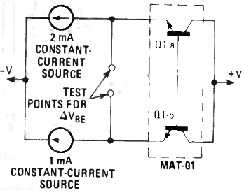
Furthermore, a number of BJTs exhibit an increased linearity on their VBE vs Ic curve compared to others. Figure below indicates a basic temperature transducer using NPN bipolar transistors MAT01.
Using MAT01 as Temperature Sensor
In this particular design, a twin transistor (a pair of matched NPN silicon transistors packaged inside a single case) like the one MAT01 is utilized. The emitters are applied with 1 mA and 2 mA constant-current (make sure to use different emitter currents for Q1 and Q2) and the output voltage roughly around 59 µV/°K.


A differential opamp becomes necessary to enhance and increase the output voltage to some meaningful value. It is advisable to calibrate the voltage range to 10 mV/°K to ensure that an ordinary voltmeter could be employed.
To execute this with this BJT sensor, the differential opamp should possess a gain of over 167. When the output voltage reaches 10 mV/°K, just about any 31/2 digit DVM could be taken to test the equivalent temperature across the transistor.
Using 2N2222 as Temperature Sensor
The accurate temperature transducer schematic displayed in the figure below, works with a ordinary op amp inverting follower configuration along with a single standard BJT like the 2N2222 with metal case.

The transistor is used like a temperature sensor probe which must have a appropriate housing like a vintage voltmeter probe grip, a small section of metal tube, and so on.
In case the concept is implemented to determine the temperature within an existing device, it could be fitted entirely inside the unit and may not require an independent housing. Nevertheless, no matter how it is positioned, a good thermal contact with the temperature that is being measured is utmost crucial.
Two DC voltage references are used for this application +/-6.2 volts. Diode D1 supplies the +6.2 V reference, while diode D2 delivers the -6.2 V reference. The +6.2 supply is coupled to the collector/base pinout of the temperature sensor BJT (Q1). Meaning, the emitter current of Q1 is going to be linearly incremental and sensitive only to temperature chnages since the collector voltage for Q1 is held constant.
This current is boosted by op amp IC1 to a level proportional to an output potential of 100 mV/°K. Variable resistor R1 can be adjusted for the calibration process to ensure the appropriate scaling level. Again, any common 31/2 digit DVM may work nicely for reading the temperatures, although the display unit is going to be in degrees Kelvin.
If you want to change the measurement to degrees Celsius, you must be aware of the fact that the Kelvin and Celsius scales are identical, but offset by 273 degrees (0° C = 273° K). To see temperature readings in degrees Celsius, an offset realignment will be required.
Potentiometer R3 switches the temperature range of the standard design from Kelvin to Celsius through summing of the countercurrent from the -6.2 V supply, using the current from the BJT.
The potentiometer is tweaked to generate zero output from amplifier IC1 with a sample temperature on the transistor set precisely 0° C.
Calibration
After the circuit is constructed it will need to be calibrated. Start by setting up presets R1 and R3 to around the center of their individual dials. Power ON the circuit, and hang on for around 5 to 10 minutes for the circuit to become stable at room temperature. In the meantime, get ready an bowl of melting ice or an "ice point bath." The ice-point of water is 0° C; (the temperature at which ice begins turning into water).
Use a common glass thermometer to validate 0° C (or 32° F) temperature of the melting ice. As soon as the circuit is stable and the melting ice bath is all set, immerse the 2N2222 transistor into the bath and wait for around 30 seconds. When you see the op amp output voltage is no longer changing, fine-tune potentiometer R3 to read exactly 0.00 volts on the meter.
Allow the 2N2222 sensor to remain in the bath for a couple more minutes, while you supervise the bath's temperature on the glass thrmometer to ensure that the bath temperature is consistent with the circuit meter reading. Once you find the output voltage is fairly constant (slight bit of deviation is tolerable), take out the 2N2222 transistor and the glass thermometer and bring them back in room temperature.
As soon as the two units get stabilized back to the room temperature (this can be verified by the reading on the glass mercury thermometer, and a complementing constant reading on the circuit's output meter reading), the final steps of calibration procedure may be completed. Alter potentiometer R3 such that the reading on meter connected to the op amp output matches with the reading on the mercury glass thermometer (you can ignore the figures on the right side of the decimal point on the meter).
Once this is completed, a 0 V output from the opamp will correspond to a 0° C, a 3 V DC output indicate a 30° C, and so on. This takes place, obviously, due to the 100 mV/°C scaling consideration. An alternative of calibration could be to use a warm water bath. Create the warm water bath by combining hot and cold water, and carry out the procedures which were discussed above for calibrating the circuit in room temperature.
Using Transistor and Diode Together
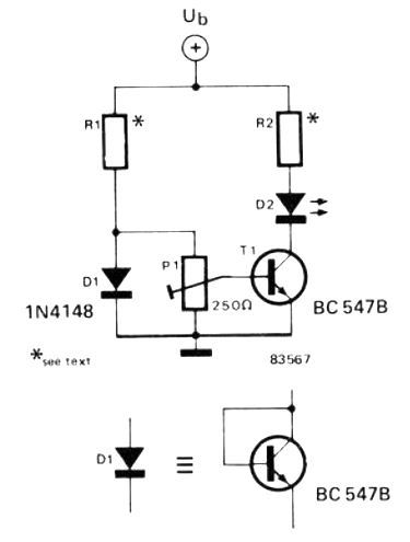
This temperature indicator design employs a transistor and a diode together in a mutually complementing mode.
The diode is kept in the ambient temperature, and the resulting voltage drop across it is used as the reference level. The temperature detection is executed by a transistor positioned near the heat source which needs to be detected.
Therefore, the transistor T1 acts like the actual temperature detector with reference to the ambient temperature as detected by the diode. This is implemented by comparing the base/emitter voltage of the BJT with the reference level from the junction of D1 and R1 through the preset P1.

The transistor will continue to be turned off so long as the temperature around it stays under a particular level, which can be appropriately set by P1.
The T1's base emitter voltage starts to drop by approximately 2 mV in response to every single degree Celsius rise in temperature around the BJT.
When the base emitter voltage of the transistor becomes lower than the voltage level at the wiper of P1, the transistor begins conducting, which is indicated by the gradually brightening light of the LED D2.
The R1 and R2 resistor values are dependent on the supply voltage, Ub, and could be determined using the following simple equations:
R1 = (Ub - 0.6 / 5) (result will be in kilo Ohms)
R2 = (Ub - 1.5) / 15 (the result will be in kilo Ohms)
For the best possible functionality of the design, it is crucial to ensure that the reference diode is positioned in the free air at room temperature, and surely never near the T1 or the heat source which is being monitored by the T1.
It should be kept in mind that no matter what, the absolute maximum temperature exposed on the transistor T1 must not go beyond 125°C if you want to keep T1 in a proper working condition.
Using IC AD590 as Temperature Sensor
There are various precision integrated circuits or ICs that are specifically designed as temperatures sensors such as the AD590, LM35 etc.
The IC AD590 is simply a two pin IC that can be procured very cheaply in a TO-18 case and also with a unique 2-pin flat casing. The device works like a temperature-sensitive current source and is scaled to read temperatures with roughly 1µA/°K.
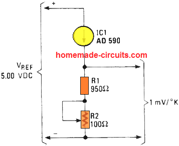
When current passed through the IC AD590 via a series a 1k resistor, causes voltage variation of 1 mV/°K (as per Ohms Law) across the resistor, in response to the corresponding change in temperature on the AD590 device.

It maybe possible to use use the AD590 temperature sensor in many different ways. One basic method is shown below, by connecting a series resistor of around 100 ohms. This design is known as a 1-temperature, or 1-point, circuit. The pot R2 can be tweaked to coincide the output voltage exactly in accordance with a standard mercury thermometer in some specified temperature.
Minor non-linear response in the device which is common in all semiconductor devices, might result in slight error at ranges far stripped away from the calibrated scale.
Another technique is to wire thé AD590 directly between a regulated +5 V reference source and the inverting input of an opamp.

The range aspect of the sensor could be set up through a feedback resistor (RF) through the formula:
Vo = (I µA/°K) (RF) (T).
We could likewise use the AD590 with a double trim-point circuit employing an op amp as explained above.

An offset current is summed up with the IC current at the inverting input of the op amp. A couple of potentiometers could be wired up, one for controlling the offset and the other one for adjusting the gain, so that the circuit could be set up using two different temperatures, and thus minimizing the error.
Using LM35
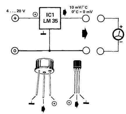
The LM35 is another high versatile and accurate temperature sensor designed to produce an output voltage that may be directly proportional to the temperature in degrees Celsius. This signifies that when the temperature is 0 °C, the output voltage will be 0 V.
The output voltage rises through 10 mV for every single degree Celsius. Meaning, if the LM35 temperature is 19.8 °C, it will provide an output voltage of 0.198 V.
It is definitely a significant edge over other temperature sensors which are designed to generate the output in kelvin. For these sensors measuring temperature in degrees Celsius demands an incredibly stable reference voltage that needs to be subtracted from the reading.
An additional good thing about the LM35 is its surprisingly low current consumption which is no more than 60 µA. This provides an extended battery life and little IC power dissipation, that ensures errors due to internal heat tend to be negligible, at around 0.1 °C with a battery voltage of 4 V.
How to Connect

You can configure the LM35 sensor directly with an analogue or digital multimeter, or, more strangely enough, to a personal computer which could subsequently process and store the detected temperature data. An appropriate software for this function can be searched online. The reliability of the LM35/LM35C is normally 0.4 °C at 25 °C. To make sure that the internal dissipation remains small, the load must be not lower than 5 k.
If an extended shielded cable is employed between the sensor and the meter, an RC configuration (a series 10 Ohm resistor with I µF) must be attached between the output of the LM35 and the ground to protect against any kind of induced oscillations.

Hello Swagatam.
Regarding your 2N2222 temperature sensor. Do you think it would be feasible to increase the sensitivity to be able to see voltage changes as low as 0.01 deg C and still have stability?
Hi David, I don’t think the mentioned circuit would be able to detect a difference of 0.01 deg C. This might require a microcontroller based circuit.
Hello Swagatam.
Thank you for your reply. I don’t want to take up your time needlessly, but can you briefly say how/why a microcontroller circuit might work when on opamp one wouldn’t? Thanks.
Hello David,
I am just guessing that a microcontroller could be perhaps customized to sense the smallest temperature difference as desired, I am not sure about it. An op amp may not be able to sense a difference below 0.1 V so it might not be efficient enough.
Sir,
I was re-reading your text on using a, “How to use diodes, transistors, ic’s as temperature sensors. Your text: “…(TO-5, and specifically the little TO-18 types) provide an improved response compared to the other variants having epoxy or plastic casing. Furthermore, a number of BJT’s exhibit an increased linearity on their Vbe V Ic curve compared to others. Figure 4 indicates a base temperature transducer using NPN bipolar transistors.” Only problem none of the drawings, schematics or graphics are numbered!
Hello Owen,
I am sorry about not indicating the images correctly. I have removed the “Figure 4” and replaced it with “figure below” so that it correctly indicates the mentioned circuit.
sir swag,
i don’t know if this is the right article i should post my query,but is related to sensor and detector.
sir, i just want a simple circuit using transistor and LED that can detect breakage in an insulated wire or cable without stripping all off.i long this since then.and you are the right person to ask to.
i just need dc source voltage ranges from 1.5vdc-12vdc. thanx
Hi Dennis,
You can check out the following article which can perhaps fulfill your requirement:
https://www.homemade-circuits.com/how-to-make-non-contact-ac-mains-phase/
Hi Swagatam,
We have been on touch in the past regarding Induction Heating, I think I ma still in the same line but a bit different if I may call it that, I have a main night light that serves also as a torch light, it is charged by means of electromagnetic field, or wireless charging and the charger is not working, I have opened it and there is a burnt resistance that I can see, is it possible to help me repair this, just the challenge that interests me. I have taken a photo of the circuit and if you would like to help I can send it to you but don’t know how.
Hi Siamak, can you please post this question under any induction heater circuit article? There you can provide your image link by uploading it on any free image hosting site. I’ll try to figure it out…