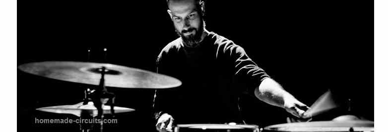
In this post we talk about a couple electronic drum sound simulator circuits which can be used for replicating actual drum beat sound electronically, using a few op amps and few other passive electronic components.
Using Capacitor as the Sensor Instead of Piezo
Conventional electronic drum kits incorporate the use of piezo disc affixed to the underside of a slim plastic membrane that functions as the drum head.
Based on the number of hits from the plastic drum sticks, the piezo disc is activated, sending the proportional amount of electrical oscillation to an amplifier for replicating the drum sound over an attached loudspeaker.
However, the disadvantage of using a piezo as a sensor is that, when you use wood or harder drumstick material, the piezo disc can break and there is no longer any beat.
We have two circuits for this drum sound experiment. Our first one will resolve the issue of the piezo sensor as well as lay a thicker material for more robust usage. Even when you use a typical ceramic disc capacitor and attempt a few beats, you can still detect an output based on the drum beats.
Basic Operation
The circuit shown in Figure 1 uses a 0.1 µF, 100 WVDC disc ceramic capacitor that is attached to the input of op-amp U1-a via a shielded microphone cable. The working details can be understood with the following points:
The tiny electrical pulses generated from striking on C1 is enhanced several hundred times by U1-a.
Its output, which is at pin 1, is supplied to the input channel of U1-b, which is predetermined as a voltage follower. U2, which is a low-voltage audio amp, boosts the signal level just enough so that a “bong” noise is produced from the speaker at every hit on C1.
We tested a variety of makes, shapes, sizes and voltages of the 0.1 µF ceramic disc capacitor and they were all very diverse.
The best capacitors examined specifically for this task were the smaller ones with a 100 V or less voltage rating.
We found values more than 0.1 µF works but they are scarce as compared to the 0.1 µF types. The smaller capacitors did not achieve the adequate output required for this circuit.
Mostly, the 0.1 µF capacitor worked very well as sensors.
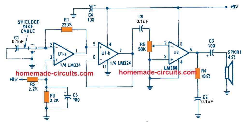
Parts List
The schematic in Figure 1 shown above is an excellent test circuit because it allows you to hear the audible tone of each capacitor as you check them. There are some capacitors which generate a short “pinging” drum beat sound whereas other have significant and longer ringing sound.
Trigger Circuit
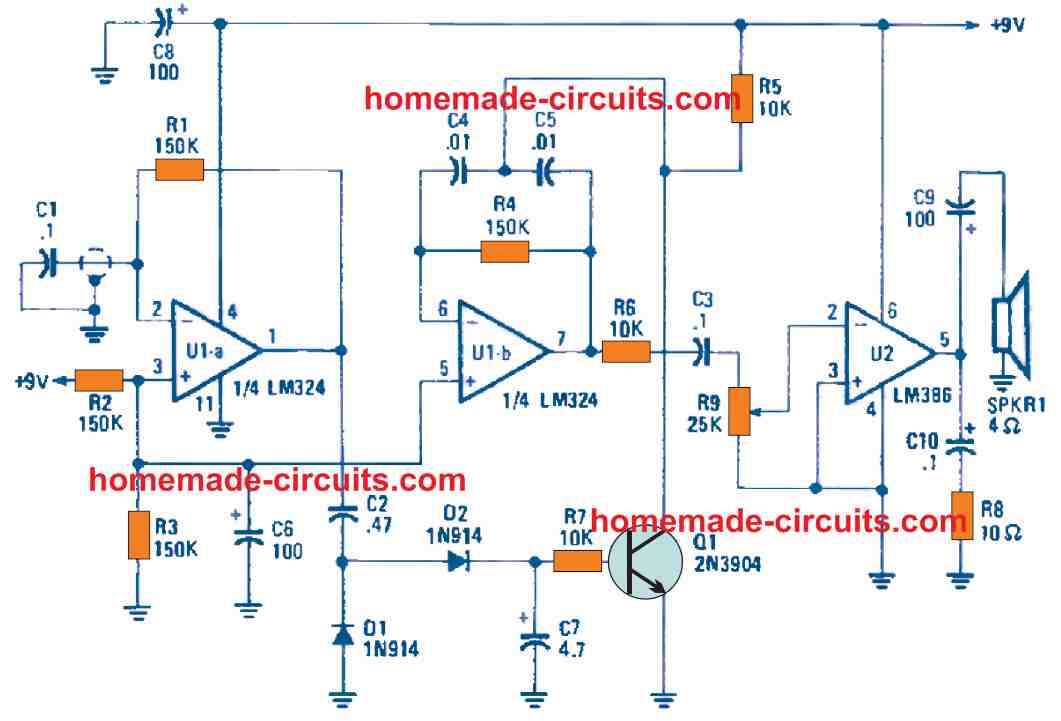
The circuit in Figure 2 shown below, encompasses a capacitor’s amplifier output pulse as a trigger signal to switch on an individual tone-producing circuit.
The dimensions, interval and magnitude of the capacitor’s output pulse is crucial because it adds to the mix that dictates the length and shape of the produced audio-output signal.
Parts List
How the Circuit Works
The electronics around U1-a is similar to the previous circuit. However, this circuit U1-a’s output is supplied to a voltage doubler/rectifier circuit which contains C2, D1, D2 ad C7. The rectifier’s output pulse delivers positive bias to Q1’s base.
The tone-generator circuit is made up of op-amp U1-b and its related components. The whole circuit will be inactive unless triggered. The generator’s output is supplied to the input of U2 (an LM386 low-power audio amplifier) that supplies adequate signal boost to power the speaker, SPKR1.
The circuit achieves a drum-like sound like with the help of the following operations.
Once C1 is hit, the signal is boosted by U1-a. Its output is then converted to DC by the rectifier circuit.
This DC output then charges C7 until the it reaches a level to turn on Q1 for a short interval. When Q1 is activated, it attaches the junction of C4 and C5 to ground, resulting the oscillator circuit to commence operation and producing the ‘drumbeat’.
The output tone’s timing is governed by the amplitude of the pulse which arrives from U1-a and the value of C7. When both or either component is increased, the ‘bang’ lasts longer. You can also shorten the tone duration by decreasing R7’s value.
The generator’s output frequency is adjustable to any audible tone by trying out the capacitor values of C4 and C5. You may choose 0.1 µF or bigger values for the low-end and 0.01 µF or smaller for the high-end variants to generate just the right note.
For a new action and appearance, the sensor capacitor can be fixed inside a drumstick that is made from a long plastic tube.
You can fix the capacitor solidly against the inside edge of one end of the tubing and place adhesives accordingly. Connect the capacitor to the circuit using a shielded microphone cable that is long enough. After that, just hit hard on any rigid surface.
Other Applications
You can use the cost-friendly drum simulator sensor for another sound application.
If your home has the door knockers, just apply some strong glue to the inside area where the knocker makes contact. Then, connect the sensor to the circuit with a shielded microphone cable. Afterwards, employ an AC power supply and you have an uncommon annunciator device with you.
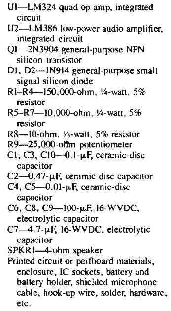
Electronic Bongo Sound Simulator Circuit
The proposed electronic bongo circuit makes use of 5 twin-tee ringing oscillator circuits which are activated simply by touching any of the attached touch plates with fingers.
This touching induces tiny electrical signals and are processed by the twin-tee based BJT amplifiers, giving rise to actual bongo like sound, which can be amplified by any standard amplifier circuit.

Percussion tools and other musical audio including bongos, drums, wood blocks, gongs are perhaps the most well-known to all of us. These musical special effect generators tend to be very appealing and complement to most contemporary music.
The Hi-Fi, depth, and tempo these types of musical sounds induce upon nearly every form of music is genuinely worth listening to and appreciated.
This electronic bongo project creates a perfect add - on to any existing amplifier system.
All the 5 unique sounds generated by this circuit is produced by specific twin-tee ringing oscillator stages. (A ringing oscillator is not really a free-running astable, rather could be activated or shot into a quick burst of oscillation by any form of spiked or pulse.)
Considering that our body builds up a certain electric charge, the oscillators are set off by simply tapping the given touch-plates using your fingers. Therefore the device could be operated in a way much like authentic bongos instruments.
Making this above discussed bongo circuit is actually very easy, and just aboiuut assembling the indicated parts over a stripboard.
The final output could be then extracted through a 3.5 mm jack into any audio amplifier for getting the hi-fi, enhanced electronic bongo sound over a suitable loudspeaker.
The 5 presets could be tweaked appropriately for adjusting and trimming the bongo sounds as per personal taste and preference.
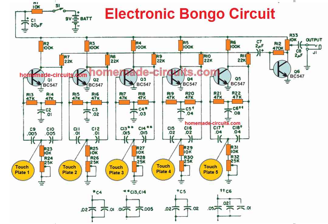
Trombone Sound Simulator Circuit
Our following circuit is a short-stroke electronic trombone, as depicted above. The main of part of the trombone is the R3 slide potentiometer.
A straightforward audio oscillator circuit is made using a couple of quad two-input NAND gates, IC1a and IC1b. This IC along with R1, R3, C1, C2, and C3 controls the oscillator's frequency.
IC1c, additionally provides the driving signal for the power amplifier. IC2, works like a buffer for the oscillator output. R4 controls the output volume of the trombone.
The slider of R3 should have a sliding lever made out of plastic or wood coupled to it. The entire circuit must be housed in a tiny plastic enclosure with the three pushbuttons, S1–S3, located in an accessible spot for practicing.
It's simple to make annoying noises on the electronic trombone. Simply operate the slider of the potentiometer while keeping one or more of the tone-control switches pressed, S1 through S3.


Comments
Hi, Swagatam.
I very much enjoy building and experimenting with your circuits.
However I am having a problem getting the Electronic Bongos circuit to work. I have built it and checked it so many times but I cannot get it to trigger. Not even with a trigger module. I can hear the speaker click when it’s connected so it’s not the audio.
Do you think that perhaps you could have a look at the circuit and tell me if something is missing? Have you built the circuit?
Thanks in advance. Tammy. 🙂
Thank you so much Tammy, glad you are enjoying my circuits.
I checked the Bongo circuit which is built using transistor Twin-tee oscillator networks and everything seems ok to me in the design.
Please note that, only the black dots in the line intersections are connected, others are not.
Did you use a powerful amplifier at the output?
hi,
i am looking for a circuit for a hearing aid.
can a circuit using an a-d and a d-a to eliminate the white noise that comes with a high gain amplifier ?
thank you
sir how about electronics drum set, which include cymbals sound
If I happen to find the design, will surely include it in the article….
do you have any twin tee drum simulators with variable decay? thank you
I have updated the information in the above article….