A crystal radio receiver, often known as a crystal set, is a simplest form of radio receiver that was widely used in the initial periods of radio. A crystal radio set does not require any external power supply to operate. Instead, it simply makes sound using the energy of the radio signals that is received. It gets its name from its main component, the crystal detector, which was initially manufactured from a crystalline material like galena. Nowadays, this part is referred to as a diode.
An antenna, a wire coil, a capacitor, a crystal detector, and earphones are all that may be required to build a very simple crystal radio receiver. Because a crystal set lacks the power to drive a loudspeaker, earphones become mandatory.
A standard crystal radio receiver circuit can be witnessed in the following diagram:
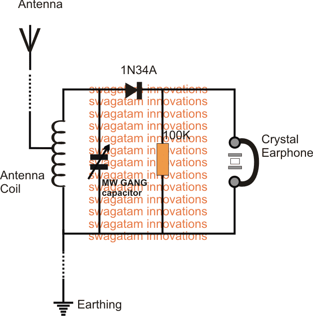
However, in this article I will elucidate the options of adding an amplifier stage to crystal radios, so that it becomes possible to use a loudspeaker instead of earphones.
Simplest Amplifier for a Crystal Set
The amplifier circuit displayed below will boost a weak or far-off station's loudness to a level that is suitable for powerful headphone listening. A DC source with a voltage range of 5 to 9 volts can be used to power the circuit.
Q1 is a BC547 NPN transistor that amplifies the signal. Use headphones with a resistance of 2000 ohms for the Z1.
Crystal Set with Loudspeaker
The circuit diagram below depicts our second amplifier. It will boost a crystal set's audio signal to a level strong enough to operate an 8 ohm speaker.
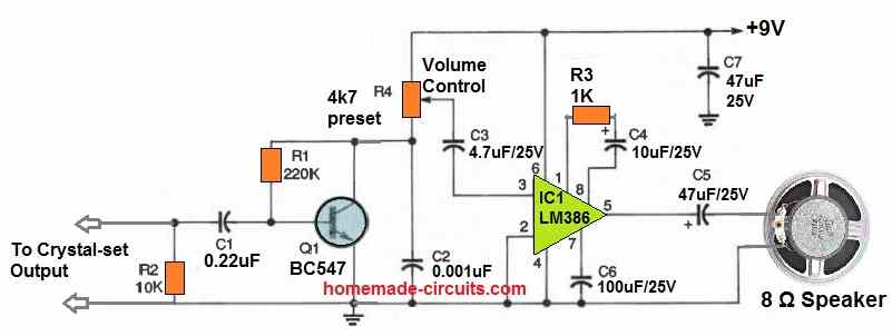
The gain of an LM386 amplifier (IC1) is adjusted to 50 when it is configured as indicated in the diagram. By eliminating R3 and connecting the positive pole of C4 straight to pin 1 of the IC, the gain may be enhanced to 200.
If a gain of 50 or 200 appears too high, the gain could be decreased to a minimal level of 20 by eliminating C4, C6, and R3.
Q1 and IC1 have a total gain of many thousand, therefore keep all of your connections short and clean. The volume can be adjusted through potentiometer R4.
Using an Antenna Coil
The antenna coil's winding diagram, which will be utilized in the remaining crystal-set receiving circuits, is shown in the following image below.
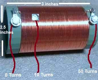
A piece of PVC pipe with a 2 and a half inch diameter may be used as the coil former. It should be around 3 inches long.
If this stuff is not easily accessible, any plastic tube with a comparable diameter and length will suffice.
Medicine containers, disposable plastic cups, and abandoned toys can also be used to make the above coils.
On the plastic former, wrap 50 tightly spaced turns using 19 or 20 gauge super enamel copper wire. At the tenth and twentieth turns, pull out a tap to finish making the antenna coil.
Crystal set with RF Amplifier
A crystal radio's output could be amplified using one of two simple techniques. One approach is to incorporate an audio amplifier at the detector's output, similar to that used in the first two concepts.
Another option is to place a radio-frequency (RF) amplifier ahead of the detector circuit, as seen in the figure below.
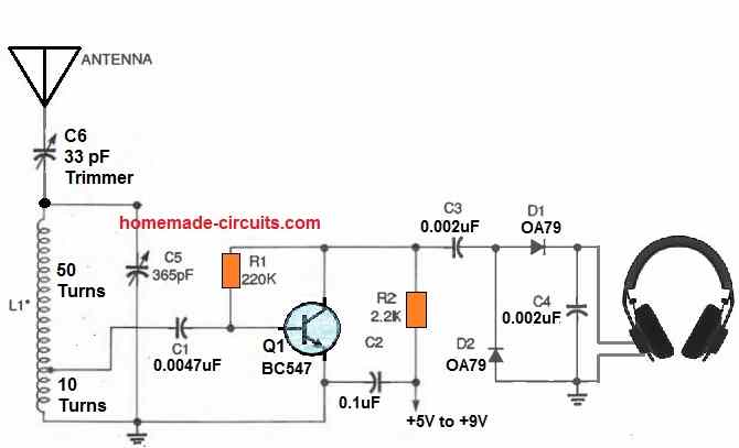
Any tunable capacitor with a value of 365 pF or more can be used as C5. This is also called the GANG capacitor, used to tune the intended radio transmission. These capacitors may often be salvaged from older AM broadcast receivers.
Additionally, you might want to look into your nearby ham radio set, where you can frequently find a decent variety of tunable capacitors and other helpful parts that are just waiting to be put to good use.
The 5 to 50 pF capacitor C6 facilitates in tuning the circuit and matching the antenna to enhance the circuit's sensitivity and selectivity.
The circuit's sensitivity can be maximized by setting C6 to its peak capacitance. Likewise, the selectivity will be at its highest when C6 is tuned to a practical minimum value.
There is always a trade-off between sensitivity and selectivity in receivers, just like in any other device.
The antenna coil L1 extracts the RF signal at the 10th turn up from the ground and feeds it to the base of Q1.
Next, the Q1 transistor boosts the RF signal to power the twin diode detector stage. Finally, the headphones Z1 enables the amplified signal audible to the ears.
Antenna and Earthing
I stretched roughly 20 feet of 24-gauge copper wire over the ceiling to serve as the antenna for this single transistor receiver. This looks quite long, but since I'm almost 100 miles away from any strong AM station, I did not have any other choice.
I had a single ground rod inserted in hard, rocky terrain for my earthing system.
This also isn't the best ground system, no doubt about it. But despite these two significant flaws, the little, straightforward receiver operated admirably. The expense of the circuit is low, and the joy it generates is irresistible.
An Improved Crystal Set RF Amplifier
Next up is an improved RF crystal set receiver circuit that is seen below. This employs an audio amplifier behind a diode detector stage, and an RF amplifier ahead of it.
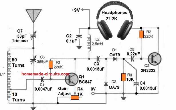
With two differences, this RF amplifier design is quite identical to the one used in the earlier receiver. Firstly, the load resistor in Q1 is upgraded to a 2.5-mH RF choke (L2).
Secondly, R4 is replaced with an RF gain control potentiometer.
At AM broadcast frequencies, the RF choke enhances the amplifier's efficiency and gain. R4 controls the receiver's level as well as the additional RF and AF amplification provided by the circuit.
How to Setup
After you've finished building the receiver, connect an antenna and ground. Apply power after setting R1 to its maximum resistance and C7 to roughly half of its highest capacitance.
Turn C6 until a station is audible, then turn R4 to a volume that is comfortable to listen to. Reduce C7's capacitance if many stations are being received at once; this should improve the circuit's selectivity.
Antenna Filter
If a powerful local station overwhelms the crystal set, an antenna filter network may be recommended.
All of the circuits above include a couple of RF-filter circuits that can help reduce interference from close or aggressive AM stations.
Despite modest differences, they function quite similarly. The antenna and reception circuits are coupled in parallel with the parallel-tuned filter circuit. This consists of a 365 pF variable capacitor parallel to the antenna coil. You can minimize or turn off the conflicting stations by tuning this variable capacitor.
You can also see the antenna connected in series with the series-tuned filter circuit. Here, a 33 pF trimmer can be seen connected in series with the antenna.
For this setup also you can adjust the trimmer to minimize or eliminate the overlapping radio stations.


Comments
Hi, have a question: Will the Crystal radio with RF amplifier work with 1.5V or 3V? It’s just a normal one transistor amplifier circuit and I don’t understand why it will not work with lower voltages than 5V. Also, I think that the Crystal radio with RF amplifier is just a simple TRF radio with a diode as the demodulator after the RF amplifier
At 1.5V or 3V, the sound volume might not be optimum, that is why 5V and above is recommended. However, the radio should work with 3V also…Yes, it is a sort of TRF. More TRF circuits can be found in the following link:
https://www.homemade-circuits.com/tuned-radio-frequency-receiver-trf-circuits/
Thanks for the reply! In the end, I used 9V, modified the schematic, and added an audio amplifier. Now it can pick up a radio station 400 km away with good volume without an external antenna, only the coil! I think it would be great if this was included in the article about TRF circuits you linked, it’s simple and has good performance. How can I send you the schematic?
Thanks for your kind contribution, I have updated the details in the following article, please check it out:
https://www.homemade-circuits.com/tuned-radio-frequency-receiver-trf-circuits/
Thank you for including my schematic in the article. I’ve always wanted to share the AM receiver circuits I’ve built. I really appreciate your help!
PS. I can send you a schematic of the receiver made in a program, so it looks better, but I need to make it because for now I only have the hand drawn.
Thanks very much for the new schematic, it looks much better than the hand drawn one. I have updated the new diagram in the same article, please check it out:
https://www.homemade-circuits.com/tuned-radio-frequency-receiver-trf-circuits/
Ok, but there’s one problem:
I forgot to add the ground symbol on the ground line in the new schematic, sorry. Could you correct that mistake please ?
Also, can you please provide the exact specifications of the coil used in your design?
I Sent the schematic of the regenerative receiver, you should have received that email by now
Yes, I have seen it, thanks very much, however it would be great if you could send a short video proof results, to let the readers know how the reception sounds…
Ok. I also made a regenerative one transistor receiver with good sensitivity, maybe even better than the two transistor TRF receiver, let me know if you’re interested.
PS. If you’re interested, I have two versions of the regenerative one transistor receiver, one with the single transistor and another one with a two transistor amplifier added to use 32 ohm headphones
Yes, of course, we are interested to see it, please send it to my email, I will post it under one of the related articles here.
Ok, i sent you an email to the adress you shared earlier. But i will repeat it here:
The coil is 610-620uH and the capacitor is 815pF (330+470pF, the extra 15pF comes from the capacitors that aren’t perfect so the capacitance isn’t exactly 330pF and 470pF). I don’t recommend using that values, I only used them because I don’t have a variable capacitor and in my country there is only 1 AM radio station on 225kHz (the name of the station is program pierwszy polskiego radia) so i didn’t add the option to tune the receiver, because it’s simpler without that and I don’t need it. You could use a 300uH coil and a variable capacitor from 30-300pF to tune approximately 530-1700kHz
Ok, if you have any more questions regarding the receiver just ask me.
Sure, I will definitely ask, if I or the readers have any related questions.
Thanks so much again, it looks great! I have updated the article with this information, please check it out:
https://www.homemade-circuits.com/tuned-radio-frequency-receiver-trf-circuits/
Sure, no problem, I have corrected it now, please check it:
https://www.homemade-circuits.com/wp-content/uploads/2021/04/simple-TRF-receiver-circuit-diagram-fully-working.jpg
It is my pleasure! Sure, no problem, You can send it to the previous email ID, I will update it in the TRF article.
Thanks so much for your valuable feedback and the test results.
Please send it to my email ID:
homemadecircuits
@gmail.com
If possible please also send a small 5 or 10 seconds test video, otherwise no worries, schematic is enough.
I Send it. Let me know if you didn’t received it
Thanks so much, yes I have received it.
Let me check and process the image and the video, once done, I will post it in the above article, and also on Youtube, and I will let you know soon.
I don’t know why so many people claim they have built crystal radios and they work because that’s not true. I tried these crystal radio circuits but they won’t work and never make a sound! I tested the tuned ferrite antenna and capacitor with a real radio to make sure they could tune in a station but when I connect the diode it kills the signal! I also tried the circuit with the RF amp but that doesn’t work either, when I connect the tuned circuit to the base of the transistor it also kills the signal! Maybe if the transistor was a MOSFET with a high input impedence that doesn’t load down the tuned circuit it might work but I haven’t tried that.
A crystal radio will work only if the radio station is very close to your location and has a very strong signal, otherwise it will never work.
However, if you are using an external amplifier and it is correctly matched with your crystal set output, then definitely you should be able to catch the weaker signals from distance also….
I finally got the amplified circuit to work a little using an air coil to tune it that is actually a Turk AM Antenna Advantage loop antenna.
It doesn’t seem to be bothered as much by connecting it to the circuit. Then I could barely hear a little sound on the strongest station and had to connect a resistor across C4 in the schematic to get the sound to work better.
Thanks for updating the results, glad you could make it work.
There are a couple of strong stations nearby that cause interference on LW and 160M but won’t come in on a crystal set! When I connect the ferrite coil and capacitor tuned circuit to the diode or the base of the transistor in the other circuit it detunes the circuit so it is no longer resonant and kills the signal! It won’t matter how strong the local stations is, this is never going to work so why do people claim it does?
poz.kristal radio ugradio sam modul GF1002 sa ic.PAM8403 problem nikako ne dobijem pojačan audio. na LM386 je sve ok. u čemu je problem
The PAM8403 is a very good amplifier IC, but maybe due to lack of a preamplifier it is not able to detect the input audio….you can try the PAM8403 at the output of LM386 and check the results…
hi swag
Ihave a annoying noise problem with LM386 amplifier have you any remedys ?
Wayne, the C2 capacitor is introduced for noise reduction, so you can experiment with it to eliminate noise, also the R3 value determines the gain of the amplifier which you can tweak to reduce the noise level.
hi swag
i dont want to connect loudspeaker to crystal set.i want to connect your simplest am radio circuit output to input one of your other circits called crystal set with loudspeaker circuit.is that possible and are their any precautions i should take.it has bc 547 transistor and a lm386 in it
Thank you Wayne, understood, yes you can do that to further amplify the AM radio output.
HI Swag
Would like to connect simplest AM radio cct to crystal set with loudspeaker cct by connecting loudspeaker wires to input of crystal set with loudspeaker. instead of crystal set .is their any reason that would not work?
Hi Wayne,
I did not understand your question, why would you want to connect the loudspeaker at the input of the crystal set?
hi swagatam
regards connecting ferrite rod core and tuning capacitor to crystal set with loudspeaker circuit would connecting one end of coil to base of Q1. other end to earth of circuit were do i connect the centre tap
Hi Wayne,
You can try the “AM radio circuit” as described in the following article, using LM386 IC:
https://www.homemade-circuits.com/ic-lm-386-datasheet-explained-in-simple/
The center tap actually goes to the antenna.
Let me know if the circuit satisfies your requirement or not.
hi Swagatam
i would like to replace crystal set in crystal set with loudspeaker circuit with MW antenna coil on ferrite rod thats in the simplest am radio circuit. would that work? please advise thank you
Hi Wayne,
Yes, that should work, you can try that.
All the best to you!!
Hello Swagatam, I have multiple questions about “Crystal Set with Loudspeaker” circuit.
1) I was wondering what the bjt circuit portion does and how it works
2) Is C1 to block out AC signal?
3) What does R2 and C2 achieve
4) How was the C5 value decided
Thank you for your time
Hello Sehyun,
1) The BJT section is for amplifying the weak antenna signals.
2) C1 blocks the DC content if any.
3) R2 is for limiting current to the circuit and C2 is for decoupling or for filtering noise.
4) C5 is the standard gang condenser used in all AM radio receivers across the antenna coil.