In this post I have explained how to build a simple yet powerful 32 watt amplifier circuit using a single chip TDA2050 and with a handful of resistors and capacitors.
By: Dhrubajyoti Biswas
Working Principle of TDA2050V
This article will detail building a stereo amplifier along with an output for a headphone jack. It is built by using the IC TDA2050V integrated circuit. According to the data sheet that comes along with the IC, TDA2050V is ideal for Class-AB based audio hi-fi amplifier.
The required operating supply voltage for TDA2050V should be in the range of +/-4.5V to +/-25V.
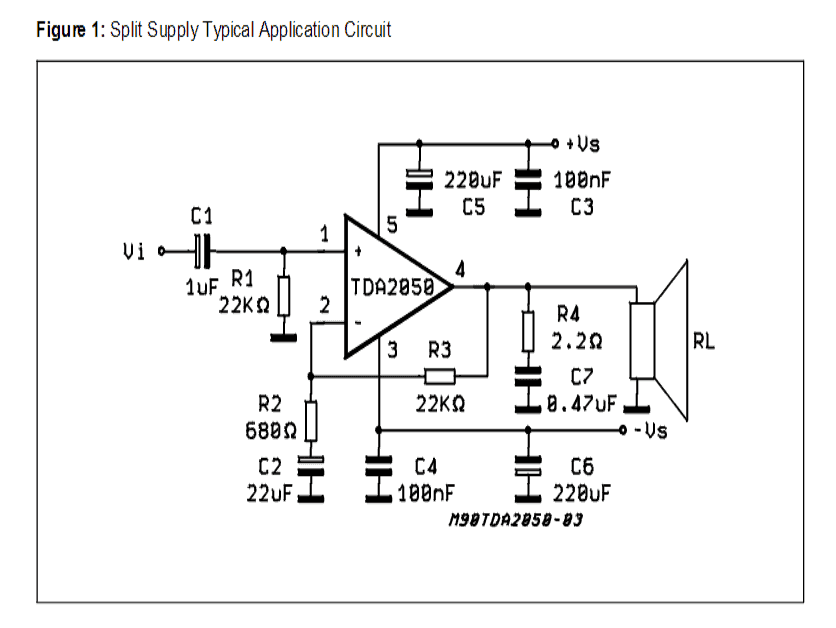
Using 25 watts of power you can achieve at least 65% efficiency. However, it is important to note that to maintain stability on the system the circuit gain should be managed with a gain of around 24dB.
We built the amplifier with an intent to use it with RB-51 bookshelf speakers. They are 8 ohms possessing a sensitivity of 92dB @ 2.83V / 1m.
Since this amplifier utilizes less power, therefore using TDA2050V is quite a right choice.
Moreover, the amplifier will also work with other audio devices, such as, tuner, mp3 player etc. It may be interesting to note that, the smaller TDA2050V chip produces a better quality sound than the bigger version.
Constructing the Amplifier
The above diagram is of an application that uses split-supply. The diagram is taken from the datasheet for ease of understanding. Also it is advisable to read the datasheet that comes along with TDA2050V chip. This will help to understand setting up the stereo in different ways.
The datasheet specified for the IC also details a recommended PCB design, which we have used as a reference for this experiment. The figure above, taken from the datasheet shows the basic PCB layout:
The amplifier that we have built in this experiment, its schematic design is presented below
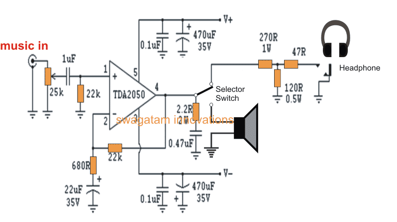
Schematic of hi-fi amplifier using TDA2050
To build the circuit, here we have followed the PCB design as shown in the above figure. Also, the circuit could be simply assembled on a perfboard.
In order to block DC current flow, we used a capacitor of 1uF MKT type. However, there is no such restriction and you are free to go for any other relevant capacitor as per your choice.
Constructing a circuit is not at complex. However, there are certain vital factors that should be kept in mind during design, as stated below:
- Grounding or earthing is very important to maintain low noise and an hum-free response from the system. This is why star grounding process is probably the best suited in this case. The system employs two ground points, use one for signal and the other for power, further connecting both of them via singular connection.
- For each channel use individual power supply.
- Keep signal wiring short and ensure the wires are twisted tightly. Maintain a distance with the AC power sources. Also it would be better if you can keep the wiring close to the chassis.
Power Supply
In this amplifier design the power supply adheres to the standard power supply regulations and employs snubbers for better safety.
Besides, we used torroidal transformer of 120VA and 18 Volt dual secondaries. Also we used 35A rectifier bridges, however, you can also use 15A – 25A bridge.
As per the design of specs, it uses MUR860 ultra-fast recovery diodes. You can also try other discreet diodes that are ultra-fast, but as per this experiment we figured out that it can be ignored and normal rectifier diodes can be used.
You can find 10,000uF capacitor for each power supply. The hum suppressed by the supply is quite inaudible albeit we could hear some on a microphone, when it has max volume and has no signal connection.
TDA2050 Power Supply Design
Cabinet
For the enclosure, here we used Hammond’s chassis [Model ID: 1441-24]– 12” x 8” x 3”, steel built and satin black in color.
The circuit board and transformer was carefully placed above just on the top of the enclosure. The volume control, headphone input and power button was placed at the front for ease of use.
We used gold-plated RCA standard jackets for the input. For output we used standard output plugs of three-way binding posts, which accepts bare wire, 4mm banana plugs or spade connector. However, please note that the binding posts of the speaker and the input jackets have their insulation from the chassis made by nylon spacers.
Heat Sink
As a standard procedure we have placed the heat-sink on the rear of the chassis, which is measured 50mm x 88mm with 35mm fins @ 2.9 C/W. Also we need to make a hole on the chassis so as to mount TDA2050 directly. As a note, please ensure TDA2050 is kept separate from the chassis because of the potential issue on TO-220 package. If this is not taken care of, then there is high chance of the chip to get destroyed once the system receives power.
In regard to isolation, you can use mica or silicon pads. Also please keep in mind to add a spacer for mountain crew to save the chip. Upon setting up the system, do finally check all the components and their placements. For instance, ensure a check to avoid continuity between heat-sink / ground / chassis and the chip.
As a conclusion, do maintain good thermal contact. Here we used thermal grease before mounting the system.
Another TDA2050 Amplifier Circuit with PCB Designs
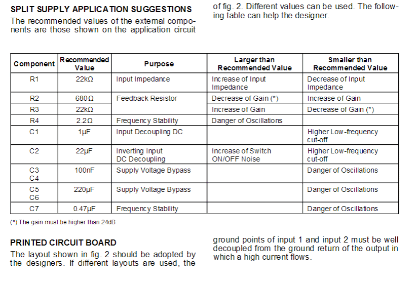
The circuit diagram as shown below corresponds to an application note from the manufacturer. The TDA2050 is a power operational amplifier capable of delivering up to 32 W at 8 Ω and 35 W at 4 Ω.
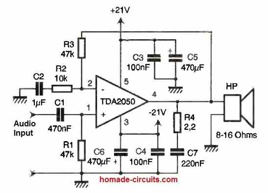
For our application, it is wired as a non-inverting amplifier with a gain of Av = 1 + R3/R2 = 5.7.
If we want to increase the gain, it is necessary to decrease the value of R2 while keeping the product of R2 and C2 constant. In fact, R2 and C2 define a low-frequency cutoff.
With the chosen values, we obtain F1 = 1/(2πR2C2) = 15.9 Hz. The low frequencies are also limited by the combination of R1 and C1 with a frequency F2 = 1/(2πR1C1) = 15.9 Hz.
Since F1 = F2, we have an overall second-order high-pass filter. The components R4 and C7 prevent the amplifier from entering an oscillatory regime. As for capacitors C3 to C6, they perform power supply filtering.
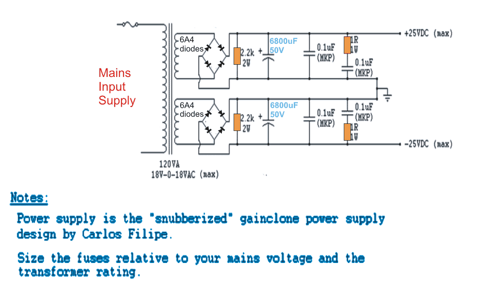
Power Supply
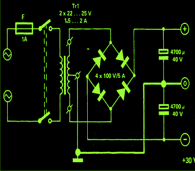
We opted for a regulated power supply at ±21V, which allows us to obtain the 30W from the operational amplifier.
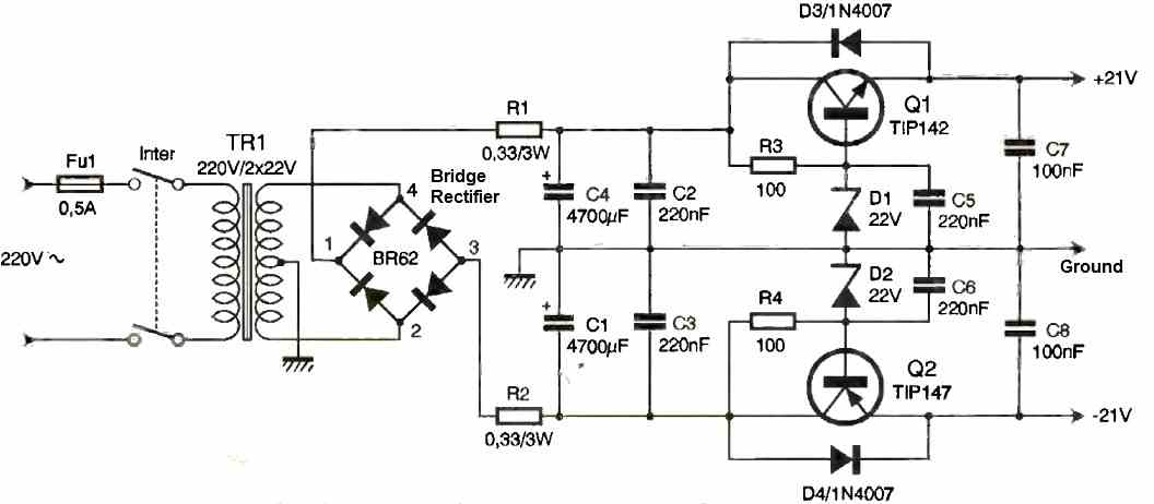
Its operation is fairly simple: a transformer provides two alternating voltages of 20V, which are rectified by a diode bridge.
Resistors R1 and R2 limit the current (I) during the initial charging of the capacitors (during power-up). This results in two DC voltages of ±26V, which we will then lower to ±21V.
To do this, we bias two transistors (Q1 and Q2) at fixed voltages, the values of which depend on the zener diodes D1 and D2 (22V). As for diodes D3 and D4, they protect the transistors from reverse voltage (when powered off).
Construction
The printed circuit board is relatively easy to make, whether using a direct etching method or a photographic method.
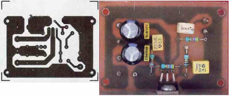
After verifying the continuity of the tracks with an ohmmeter and ensuring there are no short circuits, the components can be soldered in increasing order of size.
For both the amplifier and the power supply (Figures 4 and 6), radiators should be chosen with a thermal resistance lower than 2°C/W.
The comb-like profile is ideal, but other suitable formats can also be used depending on the board that will receive our assembly.
The power supply transistors must be isolated from the heat sink, but the amplifier circuit may not need isolation.
However, be cautious as the heat sink will be at a potential of -21V, and if you use a metal enclosure, beware of potential short circuits!
Finally, remember to attach the heat sinks to the printed circuits, as the heat generated by the amplifier and transistors can cause damage in a short period of time.
Testing
Before powering on the amplifier, it is important to verify that the diodes and capacitors are correctly installed.
No adjustments are necessary, and the amplifier is ready to operate. With 8Ω speakers, we obtain a sound of very good quality.
The power is sufficient for listening in a room of approximately 75m3, but it may not be suitable for sound reinforcement in a noisy party.
We have measured the following technical specifications:
- Output Power: 29W / 8Ω
- Frequency Range: 19Hz to over 40kHz
- Distortion: 0.5% at 25W across the entire frequency range
- Input Sensitivity: 2.7Vrms for maximum power (Pmax)
- Input Impedance: 47kΩ

Questions & Answers
Hello There! I would like ask but it’s not related on the article you posted above. Do you have any idea what kind of IC I will use for my speakers that has 3 ohms and 6 ohms (subwoofer). I’m planning to build a DIY 5.1 amplifier. It’s kinda wasted to see the speakers are just on the corner collecting dust. Hope you can give an idea. It’s really appreciated. Thank You. Hope to hear from you. 🙂
Hi, I appreciate your interest in this subject. If you are trying to build a 5.1 system, then I would recommend you the following amplifier circuit:
https://www.homemade-circuits.com/exploring-ic-tda-7560-4-x-45w-quad/
Otherwise you can try any other suitable power amplifier design from this blog, depending on the power rating of your speakers.
Please let me now if you have any further questions or doubts.
Thank you for the reply. I may add my query though. Can you tell me that it is possible for me to use my speakers (3 and 6 ohms)? Because mostly all the designs are suitable for 4 and 8 ohms only. The speakers I mention is coming from my LG home theater. Since the speakers are in good condition. I want to use them and build my own 5.1 some system. Thank you once again.
Yes, you can use them in place of the standard 4 ohm or 8 ohm, a minor difference will not cause any issues.
Okay. Can I use your subwoofer design here in the blog that is 100 watts but like I said it’s rated 6 ohms and has 75 watts rating but the total peak power rating is 120. Can I still use it?
You can try that circuit. If your speaker is rated to handle 120 watt peak then it is fine to use the referred circuit design.
But my concern is the impedance rating of the speaker because it has a 6 ohms and the design is for 8 ohms. It is okay if I use my speaker to that circuit?
It is OK, the only issue could be a slight more heat dissipation by the IC, which can be controlled by adding a suitable heatsink to the IC.
Both the speaker and the circuit will not harm if I use that kind of setup? I will follow your advice about the heatsink. And lastly, do you have a list of IC suitable for 3 ohms and 6 ohms speaker? I would like to take my time to get deeper on that matter to find answers and explanations on why most well-known brand uses the unusual impedance rather than that is already available on the market today (4/8 ohms). Thank you for the patience by answering my queries.
Using lower speaker impedance will pull extra power output from the IC causing the IC to dissipate proportionately more heat.
Using higher speaker impedance than the rated specification will do just the opposite.
There’s no other complexity involved in the concept.
Thank you for the explanation. Now I have an idea. Thank you so much.
You are welcome! Glad it helped.
I have a question: I built my amplifier tda2050 btl but there is a clipping sound when the volume is higher but it stops when the volume goes down so help me how can I fix it,I am using 8ohm/80W speaker ,4558 dual op amp and a 13.5VAC center tap Transformer
I think you can try the adjusting the value of the feedback resistor across the pin#4 and pin#2 of the IC to reduce its gain, and check the response again, and see if the problem is solved or not?
But that method sir I already tried it in the previous but it also do the same,but in my thought I think the problem could be the ground instead? Because l am not using the star grounding.
Samuel, are you you using a center tap transformer for creating the ground, for example as done in this circuit:
You can try this type of power supply if you like.
J’ai également réalisé cet ampli mais avec le tda 2030 en stéréo si je mets en fonctionnement les deux ampli à tda 2030 avec une même alimentation de + 15V et -15V avec un courant de 4A la musique n’est pas bien filtrée ça fait les parasites mais si c’est un seul ampli qui fonctionne la musique est clair je ne sais pas d’où vient le problème. Merci
Hello Daouda,
Did you build the power supply exactly as shown, with the exact part capacitor values?
Make sure to use a metallic box as the enclosure and clamp the transformer tightly with the metallic box, ad connect the Ground line of the power supply with the metallic box.
Sir,
I have a TDA 2030 bridged circute mono amp board. Can I use TDA 2050 on the same board instead of TDA 2030.
Midhun, please check the datasheets of both the ICs, if you find the ICs have the same pinout function, then you can replace them with each other.
I always put a capacitor across the transformers secondary winding,, say a 0.33uf 250v ac rated type to rid of the noise that comes down the mains…. let me digress and the picture will become clear-:
I built a dedicated fixed tuned LW/FM Radio tuned Radio 4 with a mains power supply, the racket on LW band was horrendous, after adding a 0.33uF across the secondary winding LW reception was of ‘FM quality’ – this is something I always do when building mains driven equipment. An ac rated type on the primary side I would expect to have the same effect, readers BEWARE always use the correct type of ‘mains rated’ capacitor here DO NOT use any old standard type of capacitors.
This cleans all the noises that the National grid generates, the long HV power pylons, switching voltages and stray RF pick up – not forgetting static build up, this includes arching power lines and lightening strikes that could have a short rise time of several hundred volts if not millions of volts so quick a meter will not register.
Thanks for your feedback, appreciate it!
I am skeptical that a cheap knockoff of a TDA2050 which is actually TDA2030 variant. The circuit design is nice though.
Sir, in my amplifier of tda2050. During switch off, loud speaker produce some pop sound like shhh…..
Kindly help to fix..
Hi Murugan, is your circuit built exactly as per these instructions?:
https://www.homemade-circuits.com/32-watt-amplifier-circuit-using-tda2050/
Please let us know!
Kindly let me know if I can use the center transformer in this link mentioned below for TDA2050
Split supply circuit:
——
PLease let me know ASAP
Extremely thanks for the prompt reply sir
You are welcome!
no it will not work, you must have two separate wires for the center tap, meaning the two winding should be separate and isolated. moreover the current should be preferably 5 amps
Thank you for the reply Sir. Btw TDA 2030,2040,2003,2050 and LM 3875,3876 are now obsolete and Texas Instruments doesnt manufacture them any more. So can provide the circuit with any alternative if possible?
If the stereo outputs already have a series capacitor on each channel, in that case you can directly join them together with the amp input, otherwise put a 10uF capacitor with each L/R channel outputs and connect the ends together with the amp input.
Thank you Sir, and One last question. I have stereo inputs and the output is mono so how to mix the stereo inputs?(incase of 2030/2050). I want one mono output not stereo.
Subhabrata, you ca refer to the following diagram, this is perfectly correct
But I am not sure whether the IC can be replaced with TDA2050 or not…you can refer and compare the two datasheets, if you find their pinout specs matching exactly then perhaps you can give it a try
Subhabtrata, using transistors looks easier because you can get the parts easily in the market and is fully customizable….whereas an IC can easily get obsolete or be difficult to find. also this design can be upgraded much higher levels just by increasing the supply voltage.
moreover the link which I referred involves only a handful of parts, and can eb easily assembled on a piece of veroboard, and no prior adjustments.
for a low pass filter you can refer to the following links:
https://www.homemade-circuits.com/2016/01/design-low-pass-filter-circuit-quickly.html
https://www.homemade-circuits.com/2012/02/how-to-make-simple-active-low-pass.html
Sir I have a 15-0-15 volt tranformer… But here the vltages are higher.. Is there no other alternative for using any new class AB amp ic other than transistor(circuit is a bit complex)? and what should be the circuit for low pass filter? I want the cutoff to be around 100hz
Hi Subhabtrata, in that case I think you should try the following mosfet based design, I have tested it, the output quality is superb, and you can also easily upgrade it upto 200 watts simply by increasing the supply input
https://www.homemade-circuits.com/2012/04/how-to-make-simplest-100-watt-mosfet.html
Sir I want to power a 60watt 8ohm subwoofer. Can u please modify the circuit with dual tda2050 in bridge mode?? Also please tell me the transformer specification that I need to buy. Will Ne5532 increase the gain?
If possible I will try to update it soon in website also…
Hi Subhabrata, you can find the details in the following link
http://www.diyaudio.com/forums/chip-amps/195315-bridged-tda2050-single-supply.html
Sir,
I want to used this in a car , so could you suggest the power supply in car using single battery how can I obtain +12 0-12 voltage .
Rahul, you can try the following concept
thanks sir for reply,i have used 100k pot for input & now i will replace filter cap from 4700uf to 6500uf or 10,000uf as u said.One more question sir ,can 2 tda2050 work on12-0-12 5a current because when i switch on the amp cracking sound continue coming from speaker & heatsink heating more .should i decrease the current of transformer & use 12 volt center tapped 3A current transformer? How much current need to drive 2 tda2050 stereo circuit at full volume? plz help me sir
I think the problem is not in your power supply
If your IC is getting hot even at 12V then your IC could be faulty or not an original version.
reduce the volume and check again, if still distortion persists then surely the IC has problems assuming you have done rest of the things perfectly.
i have made this stereo tda2050 amplifier split supply circuit according to datasheet on 12-0-12 5amp but music is low and lots of noise is coming from speaker .speaker is of 8 ohms & input source is mp3 player also i have made star ground. plz sir help me i dont have much knowlege about electronic i have spend lots of money & time in making this amp
are you using a volume control at the input? you should use one and adjust it for adjusting the input level correctly.
make sure the filter capacitors are large enough, above 6500uF/50V or even 10,000uF