In this article I will elucidate 7 useful yet simple automatic street light circuits using 220 V relays and solar panel. All the presented circuits can be used for automatically switching a lamp ON during night time and OFF during day time.
What is an Automatic Street Light System
An automatic street light system is a device which detects the ambient light level conditions and automatically switches an attached lamp ON/OFF depending on the level of the ambient light.
During evening when it is too dark and the light level decreases below the detecting threshold of the device, it turns ON a connected lamp to illuminate the premise.
Conversely, at dawn when the ambient light increases above the detecting threshold of the device, it turns OFF the connected lamp. This automatic ON/OFF switching of the lamp during day and night keeps repeating everyday, automatically, without any human intervention.
The light sensor used in the device is generally a photo sensitive resistor such as an LDR or photo sensitive semiconductor such as a photo-diode or a photo-transistor.
What is the advantage of an Automatic Street Lamp System?
The main advantages of using an automatic street system are as follows:
- It saves electricity by ensuring that the lamp never remains switched ON at day time, and is switched OFF when the ambient light condition is adequate to illuminate the streets naturally.
- It saves manpower by ensuring that no human intervention is required for switching the lamp ON/OFF manually.
- Removing human dependency saves money and time, allowing the system to be very cost effective.
- Being an electronically monitored system, the operating accuracy of the device is very high and efficient.
Can we Build this at Home
Yes, you can build a highly efficient automatic street light circuit at home using very few components. Even a newcomer in the field of electronics can build this circuit using very ordinary components such as transistors, resistors and a relay.
However, the person who wants to build this circuit must have all the basic knowledge of electronics and must know how to solder electronic components correctly.
1) Automatic Street Light using a Single Transistor
The first circuit diagram below shows how a reasonably good automatic street lamp could be built using a single transistor, an LDR, a few resistors and a relay.
Parts List
- All resistors are 1/4 watt 5% CFR
- R1 = 1K
- P1 = 10K preset
- LDR1 = Any standard LDR
- C1 = 220uF/25V electrolytic Capacitor
- C2 = 10uF/25V Electrolytic Capacitor
- C3 = 1000uF/25V Electrolytic Capacitor
- D1----D5 = 1N4007 Diodes
- T1 = BC547 Transistor
- TR1 = 0-12V/500mA or 1Amp Transformer
- RL1 = 12V Relay 200 to 400 ohm coil resistance
- LED Bulb = LED bulb 220V/120V, 100 watt or as per street light requirement.
The working of the circuit is simple. During day time when the ambient light is sufficiently high, the LDR has a low resistance. Due to this low resistance it keeps the transistor base more towards the positive level, causing the transistor base at the required 0.6V. The transistor therefore remains switched ON.
With the transistor in the switched ON condition, the relay also remains activated with its contacts resting on the N/O position.
Since the lamp is connected at the N/C position of the relay, the lamp remains switched OFF.
Now, when the ambient light begins to fall during evening and finally reaches a level where the resistance of the LDR increases adequately, the ground potential on the transistor base is raised via the P1, cutting off the biasing potential to the base.
When this happens, the transistor is eventually switched ON. When the transistor is switched ON, its collector becomes active and it deactivates the relay. The relay contacts change from its initial N/O position to the N/C position.
This allows the current to flow through the lamp, and the lamp illuminates.
The next morning, when the ambient light level on the LDR increases, the lamp is switched off yet again, and the cycle repeats itself everyday.
The capacitors at the base of the transistor and the relay ensure that during the transition periods (twilight) or the trip points, the relay contacts do not chatter, rather changeover smoothly.
The potentiometer or the preset can be set appropriately to determine at what light levels the relay is switched ON and OFF.
Remember, while installing the street light circuit make sure the light from the bulb does not fall on the LDR, otherwise that will lead to rapid oscillations of the relay and the lamp.
How to Set up
- Keep the preset wiper at the ground level.
- Switch ON the power supply.
- Illuminate the LDR or the premise with the required amount of light at which you want the relay changeover to happen.
- Now slowly adjust the P1 preset until the relay just activates.
- Seal the preset with quick-fix glue.
- Your circuit is all set now.
- Next, test the results by covering the LDR with an opaque shield, you will find the LED bulb switching ON instantly, and vice versa,
2) Using IC 555
Although the above transistorized is simple, its operation may not be too accurate. Meaning, the ON/OFF switching of the relay might not happen exactly at the same dawn/dusk periods.
The second design discussed below uses the IC 555 and overcomes this issue effectively.
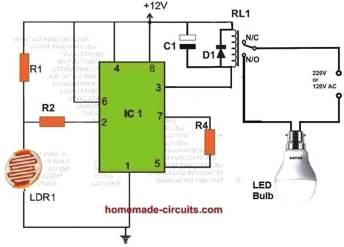
Parts List
- R1 = 220K 1/4 watt resistor or 1M preset
- R2 = 1M 1/4 watt resistor
- R4 = 100K 1/4 watt resistor
- LDR1 = any standard LDR
- C1 = 220uF electrolytic capacitor
- D1 = 1N4007 Diode
- T1 = BC547 transistor
- IC1 = 555 IC
- RL1 = 12V relay 200 to 400 ohm coil resistance
- LED Bulb = any 100 watt LED bulb or as per the street light requirement
- 12V SMPS = 1no for powering the circuit
Being controlled by an internal op amp, this IC 555 based automatic street lamp circuit is extremely accurate and will consistently switch the relay everyday, almost at the identical light levels, throughout the year.
Here, the IC 555 is not used in its conventional form, rather simply used as a comparator.
The trip point can set using the indicated potentiometer or a preset R1. R1 can be a fixed 220K resistor if no precise adjustments are required, or it can be replaced with a 1M preset for precise adjustments.
How it Works
During day time when there's ample light on the LDR, the LDR resistance is low, which keeps the pin#2 to ground level causing the output pin#3 potential to be high.
This causes the relay to remain switched OFF with its contacts held at N/C. This in turn causes the light bulb to remain switched OFF.
When night sets in, the light on the LDR decreases causing its resistance to increase. This causes a positive potential to develop on pin#2 of the IC 555, via R1. Due to this pin#3 turns negative triggering ON the relay. The relay contacts now shift towards the N/O turning ON the lamp.
The 555 IC is used as a comparator in this circuit, rather than as an astable or monostable multivibrator. To understand this fairly uncommon use, it's important to understand how a 555 works in general: When input pin 2 receives a trigger (low pulse), the output rises high. This low trigger pulse is defined as a voltage that is less than 1/3 of the supply voltage. When the voltage at the second input, pin 6, temporarily exceeds 2/3 of the supply level, the output goes low again.
Although the second input pin 6 is not used in this arrangement, the chip's output could still flip to the low state since pin 6 is linked directly to the positive supply rail.
By connecting a resistor between pins 5 and 7 of the 555, as illustrated in the circuit diagram the level of hysteresis can be controlled. The level of hysteresis is inversely related to the resistor value, with 100K being a good place to start for research. If R1 is replaced with an 1M potentiometer or preset, the circuit's responsiveness could be adjusted.
Theoretically, the circuit's supply voltage has to be equal to the relay's coil voltage. Nevertheless, do not use more than 16 V since the 555 could well be damaged. At a supply voltage of 12 V, the circuit's current usage, excluding the relay, is 4 mA. The components R2 and C1 guarantee that the relay is powered after a delay of around 2 seconds, making the circuit insensitive to sudden changes in light intensity.
How to Set Up
This above explained IC 555 based automatic street light circuit can be set up with the help of the following points:
- Replace R1 with a 1M preset. Keep its wiper fully towards the positive line.
- Cover the LDR with an opaque shield.
- Next, illuminate the area with the amount of light at which the relay changeover is required to take place.
- Switch ON power, and remove the cover from the LED.
- Now adjust the preset R1 until the lamp just switches OFF.
- Your circuit is set now.
After this, try covering the LDR with your finger and check the response, the relay should instantly activate, switching ON the bulb, and when the finger is removed from the LED, the lamp will be turned OFF.
3) Solar Street Light Controller Circuit
In some places where AC mains voltage may be inaccessible, it may not be possible to build an AC mains depended street lamp circuit. In such scenarios a solar powered automatic LED street light system appears to be a smart option.
The 3rd design below shows how a compact solar street lamp circuit could be built using minimum number of components.
It is a small 24 watt set up which can be upgraded to any higher level as per the desired specifications.
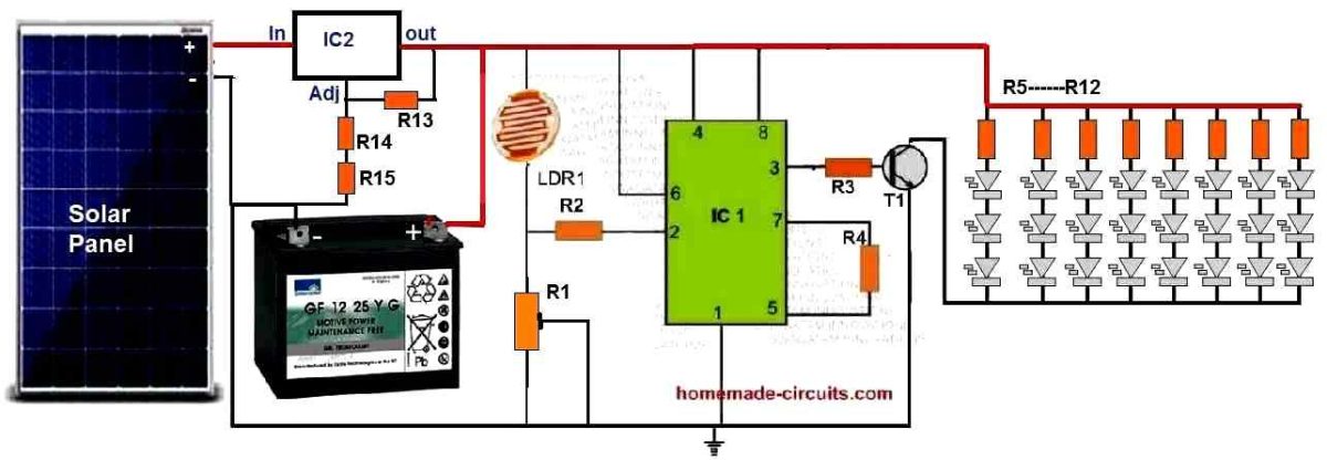
Parts List
- All resistors are 1/4 watt unless otherwise specified
- R1 = 1M preset
- R2 = 1M
- R3 = (Supply DC - LED FWD V) x transistor Hfe / LED Total Current = (12 - 3x3.3)1000 / 2.4amps = 875 ohms or simply a 1K will do. Wattage = V2 / R = 12 x 12 / 1000 = 0.144 ohms or simply a 1/4 watt will do.
- R4 = 100K
- R13 = 150 ohms
- R14 = 15K
- R15 = 33 ohms
- All LED series resistors from R5 to R12 can be calculated using the following formula:
- R = (Supply V - LED V) / LED current = (12 - 9.9) / 0.3 = 7 Ohms
- Wattage = (12 - 9.9) x 0.3 = 0.63 watt or simply 1 watt
- Therefore each resistor in series with the LEDs should be rated at 7 ohms 1 watt
- LDR = Any standard LDR
- T1 = TIP142
- IC1 = 555 IC
- IC2 = LM338
- Solar Panel = 20 V 4 amps
- Battery = 12V 25 Ah
- All LEDs = 1 watt 3.3 V high bright white
How it Works
As described in the previous section, the IC 555 is configured like a comparator. During day time when light level is high on the LDR, pin#2 potential held towards the positive level which causes the pin#3 output to be low and the transistor T1 to remain shut off.
With T1 shut off, all the LEDs also remain shut off during the day time.
At night when the light level drops on the LDR, its resistance increases causing a ground potential to develop on the pin#2 of the IC 555 via R1.
This instantly reverts the pin#3 situation and it becomes positive, which turns ON the transistor T1.
When T1 turns ON, the LEDs all light up at dusk illuminating the passage where it is installed, and effectively serving the purpose of an automatic street lamp circuit.
A solar panel is used to charge a battery via a simple LM338 based voltage regulator.
The resistor values selected for the LM338 circuit ensures that the voltage to the battery never exceeds 14.1V thus make sure that the battery can never over charge.
During day time the solar panel charges the battery to an optimal level. At night the battery delivers the required back up to illuminate the LEDs.
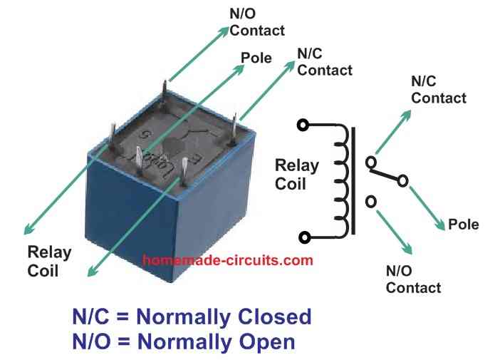
Relay Connection Details
If you are new to electronics and are confused with the relay connections shown in the schematics, then the following figure will help you to understand it quickly.
The diagram compares the schematic symbol of the relay with an actual relay pin image and clearly indicates which parts of the symbol represent which pinout of the actual relay.
4) Simplest Street Light Circuit using two Transistors
If you are newcomer and looking for a simple automatic street light system, then perhaps the following fourth design will fulfill your need.
This simplest automatic street light circuit can be assembled quickly by newbie and installed for achieving the intended results.
Built around a light activated concept, the circuit can be used for automatically switching ON and switching OFF a roadway lamp or group of lamps in response to the varying ambient light levels.
The electrical unit once built can be used for switching OFF a lamp when dawn breaks and switching it ON when dusk sets in.
How it Works
The circuit can be used as an automatic day night operated light controller system or a simple light activated switch. Let’s try to understand the functioning of this useful circuit and how it is so simple to construct:
Referring to the circuit diagram we can see a very simple configuration consisting of just a couple transistors and a relay, which forms the basic control part of the circuit.
Of course we cannot forget about the LDR which is the prime sensing component of the circuit. The transistors are basically arranged such that they both complement each other oppositely, meaning when the left hand side transistor conducts, the right hand side transistor switches OFF and vice versa.
The left hand side transistor T1 is rigged as a voltage comparator using a resistive network. The resistor at the upper arm is the LDR and the lower arm resistor is the preset which is used to set the threshold values or levels. T2 is arranged as an inverter, and inverts the response received from T1.
How the LDR Works
Initially, assuming the light level is less, the LDR sustains a high resistance level across it, which does not allow enough current to reach the base of the transistor T1.
This allows the potential level at the collector to saturate T2 and consequently the relay remains activated in this condition.
When the light level increases and becomes sufficiently large on the LDR, its resistance level falls, this allows more current to pass through it which eventually reaches the base of T1.
How the Transistor Responds to LDR
The transistor T1 conducts, pulling its collector potential to ground. This inhibits the conduction of the transistor T2, switching OFF its collector load relay and the connected lamp.
Power Supply Details
The power supply is a standard transformer, bridge, capacitor network, which supplies a clean DC to the circuit for executing the proposed actions.
The whole circuit can be built over a small piece of vero board and the entire assembly along with the power supply may be housed inside a sturdy little plastic box.
How the LDR is Positioned
The LDR must be placed outside the box, meaning its sensing surface should be exposed toward the ambient area from where the light level is required to be sensed.
Care should be taken that the light from the lamps does not in any way reach the LDR, which may result in false switching and oscillations.
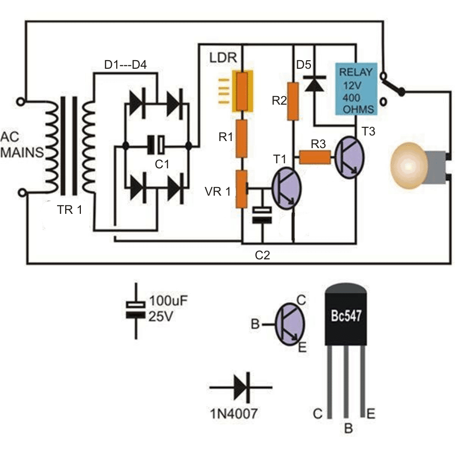
Parts List
- R1, R2, R3 = 2K2,
- VR1 = 10K preset,
- C1 = 100uF/25V,
- C2 = 10uF/25V,
- D1 ---- D6 = 1N4007
- T1, T2 = BC547,
- Relay = 12 volt, 400 Ohm, SPDT,
- LDR = any type with 10K to 47K resistance at ambient light.
- Transformer = 0-12V, 200mA
PCB Design
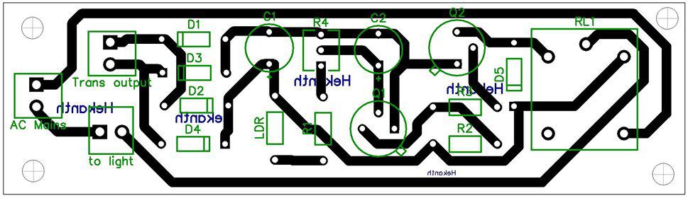
5) Using opamp IC 741
The above explained automatic darkness activated street lamp circuit can be also made using an opamp, as shown below. This is our circuit design number five:
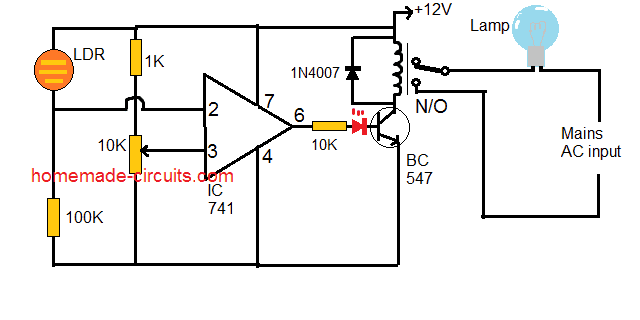
Working Description
Here the IC 741 is designed as a comparator, wherein its non-inverting pin#3 is connected to a 10k preset or pot for creating a triggering reference at this pinout.
Pin#2 which is the inverting input of the IC is configured with a potential divider network made by a light dependent resistor or LDR and a 100K resistor.
The 10K preset is initially adjusted such that when the ambient light on the LDR reaches to the desired darkness threshold, the pin#6 goes high. This is done with some skill and patience by moving the preset slowly until pin#6 just goes high, which is identified by the switching ON of the connected relay and the illumination of the red LED.
This must be done by creating an artificial darkness threshold light level on the LDR inside a closed room and by using dim light for the purpose.
Once the preset is set, it may be sealed with some epoxy glue so that the adjustment remains fixed and unchanged.
After this the circuit may be enclosed inside a suitable box with a 12V adapter for powering the circuit, and the relay contacts wired with the desired road lamp.
Care must be taken to ensure that the lamp illumination never reaches the LDR, otherwise it may lead a continuous oscillations or flickering of the lamp as soon as it is triggered at twilight.
So that's it. This concludes our article on 6 useful automatic street light circuits. If you have any doubts or queries regarding the above designs, you can express them through your comments, I will be most happy to help.
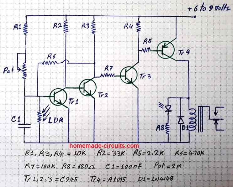
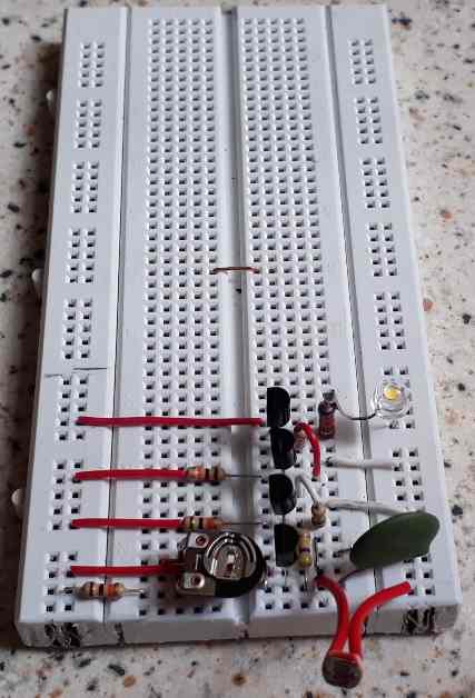
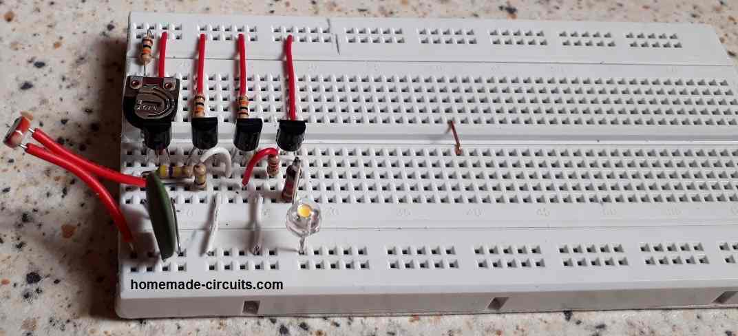
6) Highly Accurate 4 Transistor Automatic Street Light Circuit
In our 6th design we talk about a 4 transistor based automatic street lamp circuit which is highly accurate. Since 4 transistor stages are used the sensitivity and switching action of the circuit can be very sharp and precise. It means that the lamp will be switched ON and OFF almost at the same time each day.
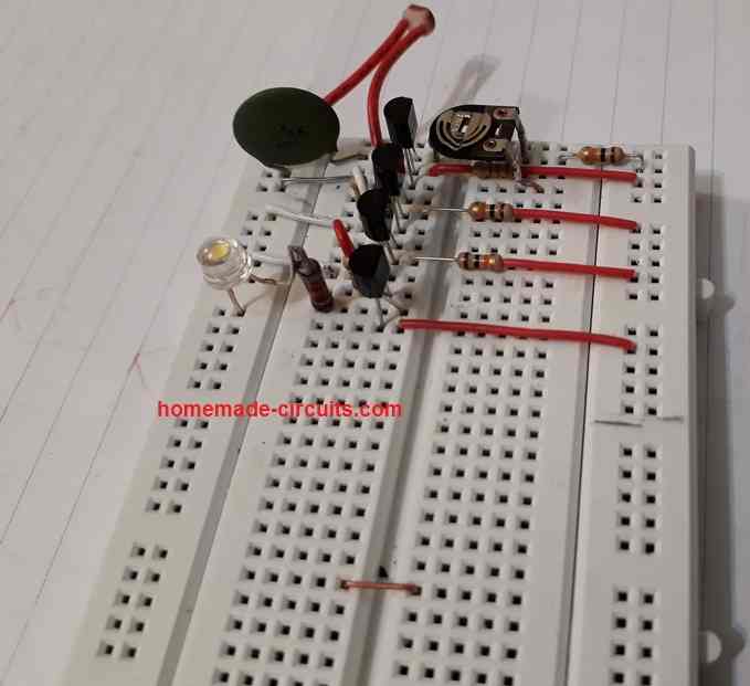
This idea was tested and contributed by "Ersa" who is a dedicated reader of this blog and a passionate electronic enthusiast. The following images sent by "Ersa" shows the neatly drawn circuit diagram and perfectly assembled board. Let's check them out.
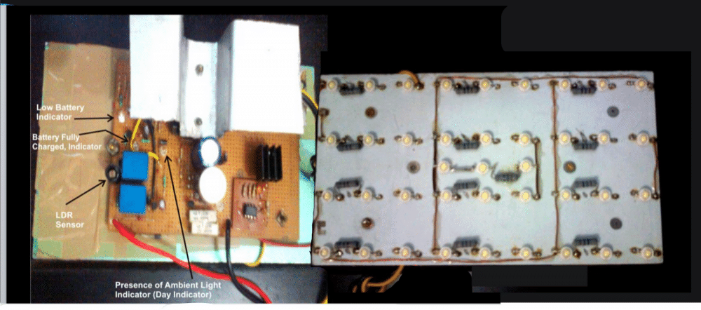
7) Automatic 40 Watt LED Solar Street Light Circuit
The 7th concept below discusses the construction of an interesting 40 watt automatic LED street light circuit, that will automatically switch ON at night, and switch OFF during day time (designed by me). During day time the in-built battery is charged through a solar panel, once charged the same battery is used to power the LED lamp at night for illuminating the streets.
Today solar panels and PV cells have become very popular and in the near future we would possibly see everyone of us using it in some or the other way in our life. One important use of these devices has been in the field of street lighting.
The circuit which has been discussed here has most of the standard specifications included with it, the following data explains it more elaborately:
LED Lamp Specifications
- Voltage: 12 volts (12V/26AH Battery)
- Current Consumption: 3.2 Amps @12 volts,
- Power Consumption: 39 watts by 39nos of 1 watt LEDs
- Light Intensity: Approximately around 2000 lm(lumens)
Charger/Controller Specification
- Input: 32 volts from a solar panel specified with around 32 volts open circuit voltage, and short circuit current of 5 to 7 Amps.
- Output: Max. 14.3 volts, current limited to 4.4 Amps
- Battery Full - Cut OFF at 14.3 volts (set by P2).
- Low Battery - Cut OFF at 11.04 volts (set by P1).
- Battery charged at C/5 rate with float voltage restricted to 13.4 volts after “battery full cut OFF”.
- Automatic Day/Night Switching with LDR Sensor (set by selecting R10 appropriately).
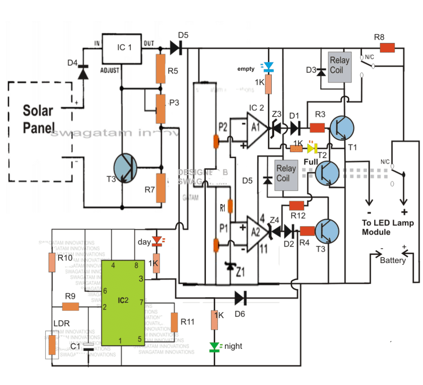
In this first part of the article we will study the solar charger/controller stage and the corresponding over/low voltage cut-off circuit, and also the automatic day/night cut-off section.
The above design can be much simplified by eliminating the IC 555 stage and by connecting the day time relay cut OFF transistor directly with the solar panel positive, as shown below:
Parts List
- R1, R3,R4, R12 = 10k
- R5 = 240 OHMS
- P1,P2 =10K preset
- P3 = 10k pot or preset
- R10 = 470K,
- R9= 2M2
- R11 = 100K
- R8=10 OHMS 2 WATT
- T1----T4 = BC547
- A1/A2 = 1/2 IC324
- ALL ZENER DIODES = 4.7V, 1/2 WATT
- D1---D3,D6 = 1N4007
- D4,D5 = 6AMP DIODES
- IC2 = IC555
- IC1 = LM338
- RELAYS = 12V,400 OHMS, SPDT
- BATTERY = 12V, 26AH
- SOLAR PANEL = 21V OPEN CIRCUIT, 7AMP @SHORT CIRCUIT.
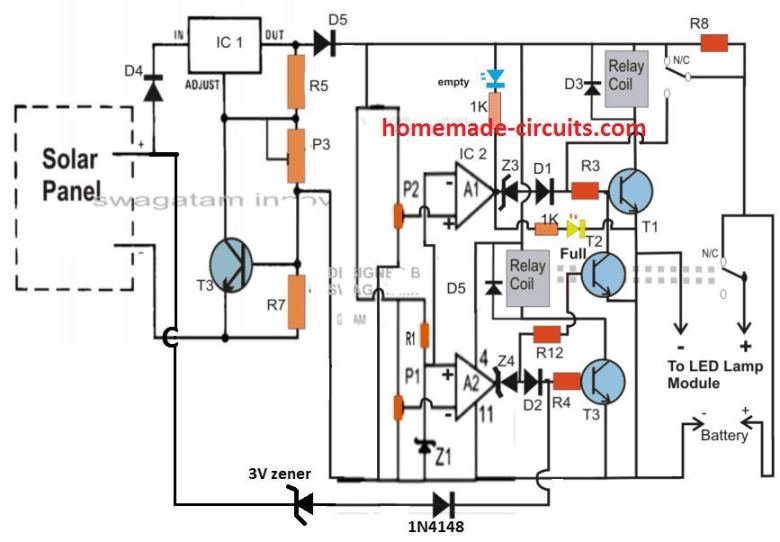
Solar Charger/Controller, High/Low Battery Cut OFF and Ambient Light Detector Circuit Stages:
CAUTION: A charge controller is a must for any street light system. You may find other designs on the internet without this feature, simply ignore them. Those can be dangerous for the battery!
Referring to the 40 watt street light circuit diagram above, the panel voltage is regulated and stabilized to the required 14.4 volts by the IC LM 338.
P3 is used for setting the output voltage to exactly 14.3 volts or somewhere near to it.
R6 and R7 forms the current limiting components and must be calculated appropriately as discussed in this solar panel voltage regulator circuit.
The stabilized voltage is next applied to the voltage/charge control and the associated stages.
Two opamps A1 and A2 are wired with converse configurations, meaning the output of A1 becomes high when a predetermined over voltage value is detected, while the output of A2 goes high on detection of a predetermined low voltage threshold.
The above high and low voltage thresholds are appropriately set by the preset P2 and P1 respectively.
Transistors T1 and T2 respond accordingly to the above outputs from the opamps and activates the respective relay for controlling the charge levels of the connected battery with respect to the given parameters.
The relay connected to T1 specifically controls the overcharge limit of the battery.
The relay connected to T3 is responsible for holding the voltage to the LED lamp stage. As long as the battery voltage is above the low voltage threshold and as long as no ambient light is present around the system, this relay keeps the lamp switched ON, the LED module is instantly switched OFF in case the stipulated conditions are not fulfilled.
Circuit Operation
IC1 along with the associated parts forms the light detector circuit, its output goes high in the presence of ambient light and vice versa.
Assume it's day time and a partially discharged battery at 11.8V is connected to the relevant points, also assume the high voltage cut off to be set at 14.4V. On power switch ON (either from the solar panel or an external DC source), the battery starts charging via the N/C contacts of the relay.
Since it's day, the output of IC1 is high, which switches ON T3. The relay connected to T3 holds the battery voltage and inhibits it from reaching the LED module and the lamp remains switched OFF.
Once the battery gets fully charged, A1's output goes high switching ON T1 and the associated relay.
This disconnects the battery from the charging voltage.
The above situation latches ON with the help of the feedback voltage from the N/O contacts of the above relay to the base of T1.
The latch persists until the low voltage condition is reached, when T2 switches ON, grounding T1's base biasing and reverting the top relay into the charging mode.
This concludes our battery high/Low controller and the light sensor stages of the proposed 40 watt automatic solar street light system circuit.
The following discussion explains the making procedure of the PWM controlled LED module circuit.
The circuit shown below represents the LED lamp module consisting of 39 nos. 1 watt/350 mA high bright power LEDs.The whole array is made by connecting 13 number of series connections in parallel, consisting of 3 LEDs in each series.
How it Works
The above arrangement of LEDs is pretty standard in its configuration and does not focus much importance.
The actual crucial part of this circuit is the IC 555 section, which is configured in its typical astable multivibrator mode.
In this mode the output pin#3 of the IC generates definite PWM wave-forms which can be adjusted by setting the duty cycle of the IC appropriately.
The duty cycle of this configuration is adjusted by setting P1 as per ones preference.
Since the setting of P1 also decides the illumination level of the LEDs, should be done carefully to produce the most optimal results from the LEDs. P1 also becomes the dimming control of the LED module.
The inclusion of the PWM design here plays the key role as it drastically reduces the power consumption of the connected LEDs.
If the LED module would be connected directly to the battery without the IC 555 stage, the LEDs would have consumed the full specified 36 watts.
With the PWM driver in operation, the LED module now consumes about 1/3rd power only, that is around 12 watts yet extracts the maximum specified illumination from the LEDs.
This happens because, due to the fed PWM pulses the transistor T1 remains ON only for 1/3rd of the normal time period, switching the LEDs for the same shorter length of time, however due to persistence of vision, we find the LEDs to be ON all the time.
The high frequency of the astable makes the illumination very stable and no vibration can be detected even while our vision is in motion.
This module is integrated with the previously discussed solar controller board.
The positive and the negative of the shown circuit needs to be simply connected to the relevant points over the solar controller board.
This concludes the whole explanation of the proposed 40 watt automatic solar LED street lamp circuit project.
If you have any questions, you may express them through your comments.
UPDATE: The above theory of seeing high illumination with lower consumption due to persistence of vision is incorrect. So sadly this PWM controller only works as a brightness controller and nothing more!
Circuit diagram for the street light LED PWM controller
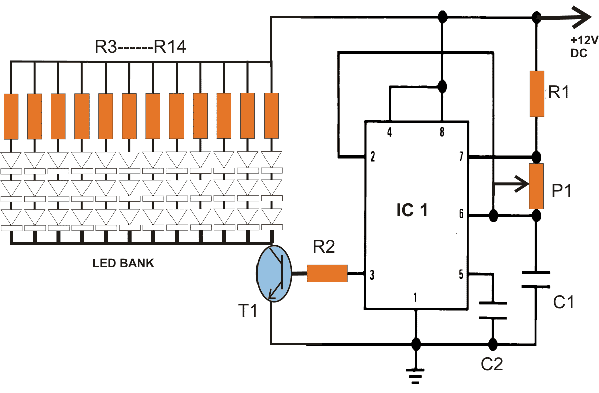
Parts List
- R1 = 100K
- P1 = 100K pot
- C1 = 680pF
- C2 = 0.01uF
- R2 = 4K7
- T1 = TIP122
- R3----R14 = 10 Ohms, 2watt
- LEDs = 1 watt, 350 mA, cool white
- IC1 = IC555
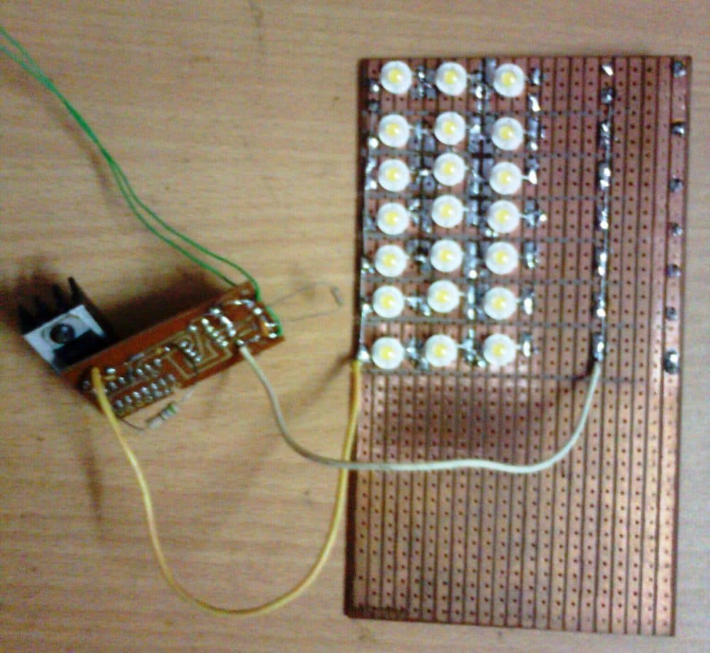
In the final prototype the LEDs were mounted on special aluminum based heatsink type PCB, it is strongly recommended, without which the LED life would deteriorate.
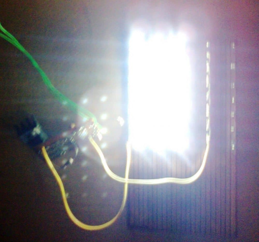
Prototype Images


Questions & Answers
please recheck the diagram because it’s indicated switch not LDR, sorry to disturb
That switch is optional, you can remove it if you want, and replace it with short link.
I have included it for an optional manual ON/OFF operation.
If you don’t want the AUTOMATIC day/night detection, then you can remove the BC547 and its base resistor network, and use the ON/OFF switch for the manual toggling of the LEDs.
please try to rate the resistors going to the LED lights and you first create a circuit using LDR in case I may want the switch to be automatic turn on/off
This circuit is automatic, and will automatically switch ON the LEDs when it is sufficiently dark…
Please provide the LED specifications, I will calculate the resistor…
please design 100w solar panel charge controller minus a relay that can charge 70ah battery please make it simple
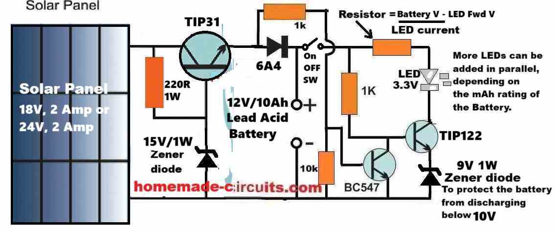
The previous circuit (below) which I suggested can be modified for any solar panel and battery, just by changing the solar panel, LED and the transistors.

I want you to create a circuit for my project of making street light solar that doesn’t use a relay but I want the LED bulb watt to be 20w or 30w , solar panel 10w, battery 12ah , please design it in two ways, the first way without automatic switch and the second way with automatic switch, please make it very nice power saving so it can protect and keep the battery so it can stay for a longer period of time
Here’s the complete circuit diagram for your specified requirement:

Please let me know if you have any further questions…
Hi Swagatan, Thank you so much for your tireless assistance and patience with beginners electronic enthusiasts, – it’s really appreciated. In one of your ” 7 Automated Streetlight Circuits”, I am building the No 2 cct, using a Ne555. The only question I have, is where the 10k resistor (R3), mentioned in the parts list, fits in?
Kind Regards and keep up the awesome work!!
Thank you so much Pieter for your kind words,
I am sorry about the confusion, as far as remember the 10k is nowhere present in the 2) diagram using IC 555, so please ignore it.
I have removed the 10k from the parts list now.
Please let me know if you have any further issues with the circuit…
Hello, good afternoon. All the public lighting circuits are very good. But I’m looking for one that has the peculiarity of being able to turn it off with a button… I mean, it turns on only when night comes but when I want to turn it off I can do it with a button, it has to stay off until the next day when night comes again … From already thank you very much.
Hi, yes that’s possible.
You can implement it in the following manner.
Select any circuit which has a transistor relay driver for controlling the lamp.
Now connect an SCR between the base of the transistor and ground, in the following manner:
Anode to transistor base.
Cathode to ground line.
1k between gate and ground.
A push-to-ON momentary switch between gate and the positive through another series 1k resistor.
SCR can be a BT169.
I will try to do it soon
Good morning Sir, thanks for all you do.
Please Sir I need a circuit for 3v DC source to automatically power 3v 50watt DC light, that will not affect the illuminousity of the light. I have tried various transistor connection but they tend to reduce the brightness of the LED.
Thanks
Thank you Evangel,
You will need the input current to be at least 50 / 3 = 16 amps to ensure the LED illuminates brightly. Are you supplying this much amount of current?
Yes Sir,
I need the circuit to work fine with this specifications.
Thanks ????
To switch 16 amps you will need one of these transistors, as mentioned in the following datasheet:
https://www.onsemi.com/pdf/datasheet/mj11028-d.pdf
Thank you Sir.
I am very grateful.
I will give it a trial
No Problem, Evangel. all the best to you!
Thanks for your impact so far,
I am finding it hard getting the recommended transistor you suggested, can I try 2N3771 transistor?
2N3771 will not be suitable, because it is just 20 amp and the not a Darlington transistor.
You can try building a Darlington transistor by combining a TIP35 and 2N2222 transistor and see if it works or not.
I hope you know how to connect these two transistors in Darlington pair.
No I don’t Sir, please help me with the circuit.
Thanks ????
Here’s an example of how to create a Darlington pair transistor:
I’ve laid the IC555 circuit perfectly, except I used a white LED and a 1K ohm resistor in line with the relay. The circuit activates and the light turns on, but I cannot utilize the photo resistor. It is not activating properly. The circuit stays energized all the time. Is there anything I can do to fix this?
Thank you.
The 555 based circuit is a tested design, you can see the video proof for the IC 555 design.
As there are hardly any components used in the IC 555 design there’s nothing I can suggest to troubleshoot.
You can manually short circuit the LDR terminals and check whether the IC responds or not?
What is the pin configuration of ic324 as used in the circuit above .
Use any two op amps from the LM324 and join the Vdd and Vss pins to the supply lines. You can also use LM358 IC.
Dear Sir Swagatam
Hello. A few years ago, I bought a house light circuit consisting of four transistors. I put aside its printed circuit board and mounted all components except Relay, LDR, and power supply, on a bread-board so that I can easily substitute the components in case they became defected later. I also took a few pictures of it for a future like today. Since it has been working well till today; meaning it has switched on the lamp by sunset and has switched it off the next morning; I decided to draw its circuit diagram and send it to you. Perhaps it would possibly be interesting for you and your visitors.
He who never forgets you for a lot of things that he has learnt from you,
Ersa
Thank you so much Dear Ersa,
I greatly appreciate your contribution!
The images and the circuit diagram look very nice and perfect.
I have posted the images at the end of the above article, I hope the readers will like them very much.
Many thanks once again.
Dear Sir Swagatam
Hello. it is my pleasure you liked the circuit. Thank you so much for your kind words and publishing it.
Wish you all the best
sincerely yours
Ersa
It is my great pleasure Ersa, thank you so much for your kind contribution!
Thank you very much for your inovative ideas.
All your design are very well understood.
But I have one problem.
Please how can I purchase the various components needed to build the board?
Thank you for your kind feedback, appreciate it very much!
You can buy the parts from your nearest local spare part dealer, or you can visit any online electronic spare part store and order the parts online from those stores.
Thanks for this. I hope a TRANSFORMERLESS version of this is possible using a capacitive power supply
That’s a good idea, yes a transformerless version can be also created, if possible I will try to update it in the article.