The IC LM321 is the single op amp version of LM324 which is a quad op amp IC and carries 4 of these ICs in one package. Therefore for applications which demand a single op amp with the attributes of the versatile LM324, in such cases this single op amp can be utilized effectively.
For more info, you can refer to the original Datasheet of the IC LM321
Why LM321 is Better than LM741
The LM321 IC is extremely versatile, it can be easily replaced with our very own, the ubiquitous IC 741.
Although IC 741 is also a good opamp IC, LM321 outmatches it due to its wider operating voltage range which extends right from 3V to 32V with a single supply, that implies for dual supplies this IC can work with voltages up to 64V.
Other in-built features of this IC include:
- Gain Band-Width Product - 1MHz
- Minimal Supply Consumption = 430uA
- Small Input Bias Current = 45nA
- Stability even with high capacitive loads and currents
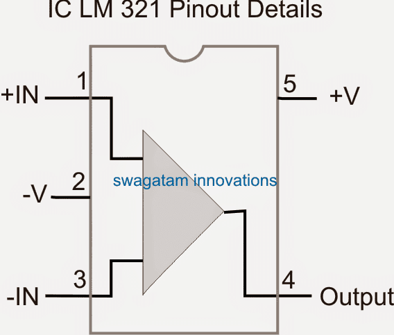
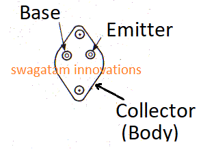
IC LM321 pinout Details
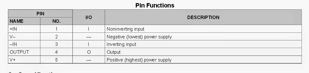
Pin Functions of the IC LM 321
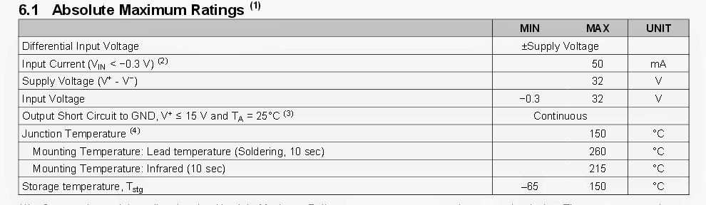
The Absolute maximum Tolerable or Breakdown Limits of the IC can be studied from the following Table:
Technical Description
The LM321 provides efficiency and cost effectiveness to low power devices. With a superior unity-gain-frequency along with a designated 0.4-V/ps slew rate, the quiescent current is barely 430-pA/amplifier (5 V).
The input common mode range consists of ground as well as the unit has the ability to perform in single supply purposes not to mention in dual supply applications too. Additionally it is competent at conveniently handling significant capacitive loads.
The LM 321 comes in the SOT-23 packet. In general the Ll/l321 is a low power, broad supply range efficient operational amplifier which can be engineered into a variety of products at a relatively inexpensive cost without affecting precious floor area.
How IC LM321 Works
The LM321 operational amplifier may work with a single or dual power supply voltage, carries true-differential inputs, and continues to be in the linear format with an input common-mode voltage of zero VDC.
This amplifier performs over a wide selection of power supply voltages, with minor difference in overall performance aspects. At 25°C amplifier functionality is achievable right down to the very least supply voltage of three volts.
Substantial differential input voltages could very well be lodged and, as input differential voltage protection diodes are not being used, simply no large input currents originate from big differential input voltages.
The differential input voltage could be bigger than V+ without causing damage to the device.
Safety ought to be offered to reduce the input voltages from heading negative in excess of -0.3 VDC (at 25°C). An input clamp diode with a resistor to the IC input pinouts should be considered.
Characteristic Information
To decrease the power depletion, the amplifier bears a class A output stage for smaller signal levels which transforms to class-B in bigger signal formats.
This permits the opamp to both supply and sink significant output currents. For that reason both NPN and PNP outer current boost transistors may be used to stretch the power potential of the fundamental amplifiers.
The output voltage ought to increase up to 1 diode decrease above the negative rail to bias the on IC vertical PNP transistor for output current sink functions.
For AC usages, wherein the load is capacitively connected to the output of the amplifier, a resistor needs to be put into use, from the output of the amplifier to the negative to maximize the class-A bias current also to cut down distortion.
Capacitive loads which are usually employed right to the output of the amplifier help reduce the loop balance margin. Magnitudes of 50 pF might be adjusted making use of the worst-case non-inverting unity gain connectivity.
Massive closed loop gains or resistive isolation ought to be employed in case massive load capacitance needs to be powered by the amplifier.
The bias configuration of the LM321 creates a supply current that could be independent of the strength of the power supply voltage over the range of from 3 VDC to 30 VDC.
Output short circuits possibly to ground or to the positive power source needs to be of brief time period.
Devices could be damaged, not as a consequence of the short circuit current leading to metal fusing, but instead on account of the massive rise in IC chip dissipation that should result in inevitable malfunction on account of extreme junction temperatures.
The more substantial value of output supply current that could be within 25°C presents an increased output current functionality at increased heat compared to a typical IC operational amplifer.
Device Functional Modes:
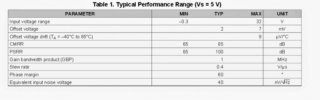
Common-Mode Voltage Range
The input common-mode voltage range of the LM321 series extends from 300 mV below ground to 32 V for normal operation. The typical performance in this range is summarized in Table 1:
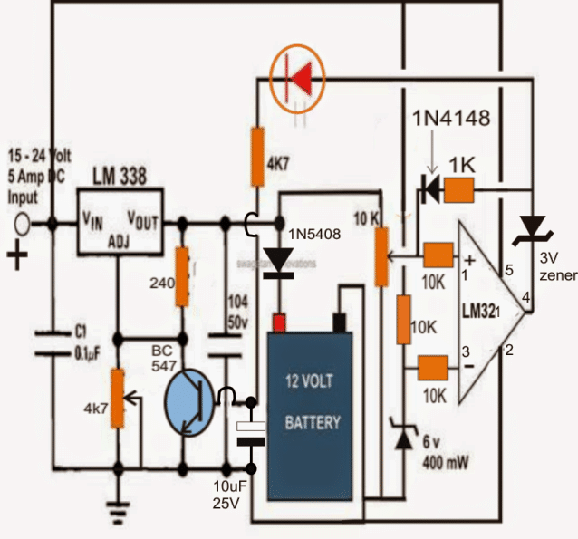
Application Circuit using IC LM321:
I have discussed many IC 741 op amp based circuits, typically these include the battery chargers where the op amp can be seen effectively implementing the essential automatic high and low charging level cut offs.
The above discussed IC can be also used in place of the IC 741 for getting identical results.
A typical automatic battery circuit using the IC LM 321 application can be learned from the following diagram:

Questions & Answers
Hi Swagatam, First off allow me to thank you for the diverse range of topics covered by your website.
regarding the operating voltage of the LM321, I thought it was important to point out that operation from 3 to 32 V does not imply operation of +/- 32V ( or 64V as stated )
What is actually implied is that 3 to 32 can also be +/- 1V5 to +/- 16V
Keep up the good work!
Thank you Gasboss,
You are correct, actually 32V is the plus to minus voltage, meaning the positive and the negative limits are +16V, and -16V respectively.
please help me with circuit diagram for lithium ion battery charging circuit of 25 volt 20 ampere current .
You can try the last circuit from the following article:
https://www.homemade-circuits.com/usb-automatic-li-ion-battery-charger/
1) Replace the relay with a 24V 30 amp relay.
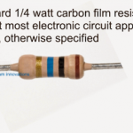
2) Replace all 1k with 4k7 1/4 watt resistor.
3) for the input supply use an SMPS with a constant 25V, and constant current 10 Amp.
could you provide me with another battery charger circuit, i cant find the lm321 in our local market here.
you can use IC 741 instead
Thanks for the information. I would like to know if the diode in red in the battery charger is LED? . More so I would like to have some other circuits like inverters, amplifiers, etc. I look forward to hearing from you
yes that’s an LED. There are many inverter an amplifier circuit n this website, please check the categories in the sidebar.
Your contribution is very excellent and awesome providing step by step in depth to the field thank u
It’s my pleasure!!
Hello sir
For this IC when inverting is greater than noninverting output is high right.
Am looking to see if I can get it here.
that's right Michael, the rule is universally true for all opamps
Pls how do I set the upper and lower charge level?
without connecting the batt adjust the 4k7 pot to get the required charging voltage across the battery points…then adjust the 10k preset such that the LED just lights up for setting the over charge threshold…do this with the feedback 1N4148 disconnected, connect it back after its done. the series resistor with the 1N4148 can be tweaked to determine the low voltage restoration.