This circuit is designed to sense the whistles from a pressure cooker and count the number over a digital display. The system relieves the user from the stress of constantly monitoring the cooker and from manually counting the whistles.
The idea was requested by Mr. P.K. Bajpai
Design Concept
In many of the Asian countries rice is the staple food and to cook rice efficiently a pressure cooker is normally employed. We all know that a pressure cooker is preferred since it is able to cook food quickly through its high steam pressure inside. This saves energy and time both for the user.
Another advantage of this special cooking vessel is the facility to adjust the cooking degree or consistency of the food ingredient through an audible alarm in the form of whistles, also created by steam pressure. The number of whistles allows the user to understand and optimize the texture and the efficiency of the food inside the cooker, and if this is not correctly estimated results in a bad quality food or sometimes even complete destruction of the food.
Electronic Counter for Counting Whistles
As per the request I have designed a simple and cheap whistle counter circuit that will relatively accurately respond to cooker whistles and trigger a digital counter for generating the data over the display.
How the Circuit Works
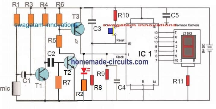
Referring the image above, the design is basically built using two stages, a sound sensor circuit comprising T1, T2, T3, and a digital clock counter circuit using IC 4033.
The original circuit of the sound sensor was actually an ordinary MIC based amplifier designed to pick all sorts of sounds, and therefore the same design did not appear desirable for this particular project, since here I needed the device to sense only the high pitched whistles and not any other form of sound disturbances.
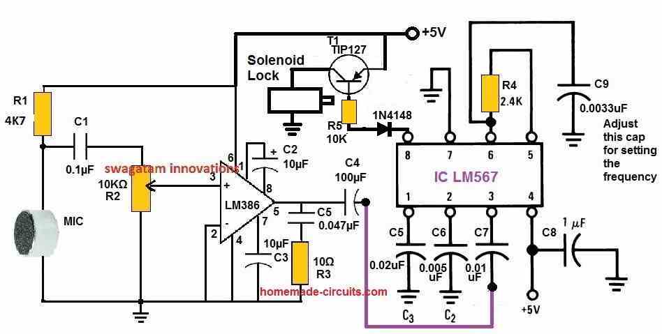
To modify the sound sensor into a customized whistle sensor I initially thought of applying LM 567 concept so that it filtered only the specific sound frequency.
However I did not want to make the design too complex, rather wanted to keep it simple and cheap, yet reasonably accurate.
This led me to think of an alternate solution using an opamp based high pass filter, but even this could have made the design complex, therefore ultimately I ended up designing a passive high pass filter using a capacitor and the resistor network for accomplishing the purpose.
You can see this inserted in the form C2/R7. This network makes sure that the only the high pitched, high frequency noise is able to pass through T2 and reach T3 for further amplification.
Other lower frequencies will be simply cut off and not allowed to cross the C2/R7 stage.
Before drawing the schematic I confirmed the result by imitating and creating sharp verbal hissing sounds over the MIC, I was happy to see the connected LED effectively turned ON only to these noises, whereas the other normal loud sounds hardly succeeded to produce any effect. This confirmed the sound filter stage perfectly.
However the counter is not practically checked by me, but I can assure that it will work, since the design is a standard IC 4033 digital counter application design.
Parts List
- R1 = 5k6,
- R3 = 3M3,
- R4, R8 = 33K,
- R5 = 330 OHMS,
- R6, R2 = 2K2,
- R7 = 470K,
- R9 = 10K,
- R10 = 1K,
- R11 = 470 Ohms,
- C1 = 0.1uF,
- C2 = 330pF,
- C3, C5 = 0.1uF ceramic
- T1, T2 = BC547,
- T3 = BC557,
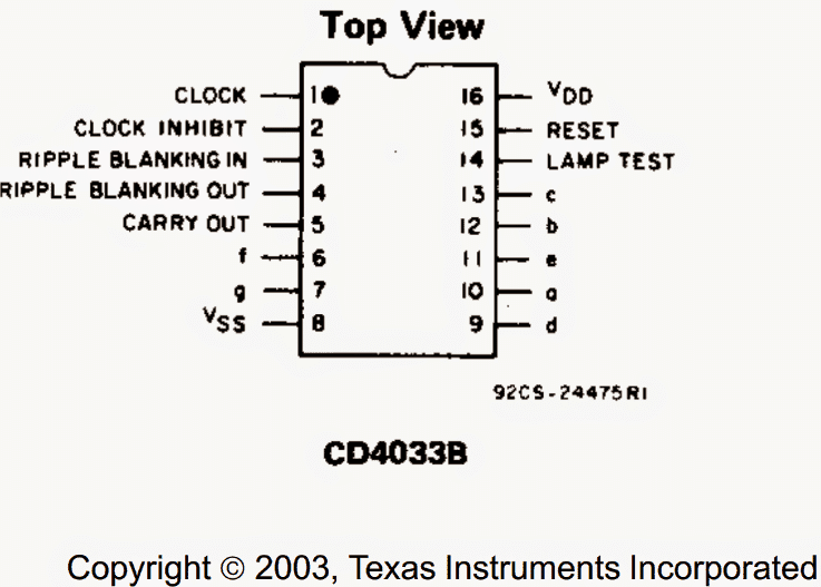
- IC1 = 4033
- Mic = electret condenser MIC.
- Display = 7 Segment Common Cathode Type,
- Push Button = Push to ON type,
- Battery = 9V PP3 with switch
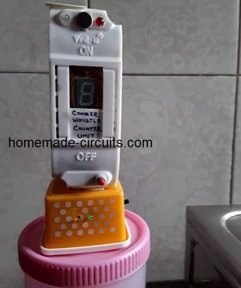
The Circuit was Successfully Tested and Built by Mr. Pradeep Bajpai. The images of the built prototype can be witnessed below:
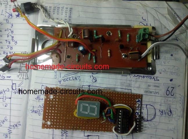
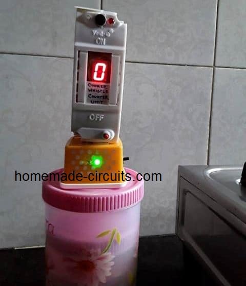
Video Clip: The working proof of the above whistle sensor can be seen in the video which was also contributed by Mr. Pradeep Bajpai.

Questions & Answers
Congratulations for a good invention. How can I buy this. Can you please share your number in my mail sevaserve@gmail.com
thank you!! and glad you liked the project, however,I am sorry we don’t sell electronic product from this website
Hi Swag,
Thank you for sharing this beautiful circuit, I want to keep a buzzer where it should raise alarm when cooker whistle count reaches 5.
I want to set the whistle count and also once it reaches the count, it starts alarming.
Please help me to complete the above features.
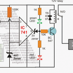
Thank you Yugesh, you can add the following circuit with the main circuit. Connect pin14 with the collector of T3. Also please connect a 10K resistor across pin14 and ground, which I forgot to show in the following diagram:
Hey, few days ago I was thinking of exactly making whistle counter for pressure cooker. Today when I was thinking of how to make it possible, I searched on internet and found your website. I can’t believe to see that this idea only exists.
Can you please teach me how can i make this whistle counter for my pressure cooker from scratch? I would be more than happy if you assist me or share how did you exactly make this? I don’t have much knowledge about digital circuits.
Please email me if you are interested in assisting me.
Hi, If you are a newcomer in the field of electronics then you may have to learn how to read the electronic symbols and the schematics, and all the basics working of the components. Without learning the basics it can be impossible to build the above or any electronic circuit.
Sir ,can u please tell full description about capacitors used in this exp,(confusion about ceramic or electrolyte….)
Sai, the caps with two black blocks are ceramic, the capacitor with black and white blocks are electrolytic
Nice project, i want to purchase, complete device
Mob 8871631562
Sir !! I need the circuit diagram for this project sir!! Will u plse send it ..
Thank you advancely for your help sir!!
hello, Can you mail be the Report of this project.
which report?
How the sound is used for counting purpose?
why we have used Reset switch?
explain the detailed working of IC and its display, we have already went through the content but did not understand.
how much voltage we have to provide through the mic?
reset switch is for resetting the display to zero manually using the push button.
Supply voltage is shown in the diagram, it can be between 6V and 12 V.
for the IC details you can read the following article:
https://www.homemade-circuits.com/making-electronic-scoreboard-using-ic/
Sir, If, I want to reset the circuit after 5 whistles, how can I do?
And also I am not getting where exactly the LED is?
Radhika, resetting before 9 count can be difficult because the output of the IC generates complex voltage for the display which cannot be used as feedback for the reset pin. LED is at the collector of T3
Hello sir, I really appreciate for your efforts for making such useful circuits like pressure cooker whistle counter. Sir Can I contact you by email or phone\Message?
Thank you Chandan, You can discuss your queries through comments, you will expect quick replies here!
What if I needed more than 9 whistle?
You will have to cascade 1 more 4033 IC to get a two digit display
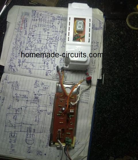
Hi Swagatam ji ,finally I have assembled Pressure cooker whistle counter as per ur precious guidelines. I have made pcb by etching copper clad board by myself for easier assembling of components.I want to show u it’s pics and a video. I opted a single MCB housing as it’s cabinet . Provision to run on a 9v battery as well as 5v adopter has been made . LED indicators , to show that unit is running on battery or on adopter are also there. The max. range of operation is about 6- 7 ft .It works more efficiently when placed 2-3 ft distance. When it is moved beyond 2-3 ft it picksup surrounding noise and shows wrong counting of whistle . It also picksup sound of kitchen utensils or clicking of finger / clap . Can I send u video and pics on facebook?
Dear pk ji,
how had u made 5v adoptor ?
That’s great Pradeep ji, I am glad you could make it successfully.
Yes the response may not be extremely precise since we have not employed any special frequency detection stage. Nevertheless, you can adjust the response by suitably adjusting the values of C2/R7. Increasing R7 value or decreasing C2 value appropriately will help to reduce the unit’s sensitivity for other noises.
Initially you can try replacing the existing R7 with a 1M resistor and check the response, and then accordingly fix the most favorable value through some trial and error.
Dear Swagatham
Many people forget to count whistle.!!!!!!!!! So this is a very very useful circuit in kitchen.
As per Mr.Pradeep Kumar Bajpai’s experiments, 2 to 3 feet range is too short, means the condensor mic will be almost close to the steam from pressure cooker. This steam/moisture may cause damage to condensor mic.
Any solution for this problem…..?
I will also make this circuit.
NB: CD4026 can be used instead of CD4033.
Regards
Thank you Anil,
However I think 2 to 3 feet is quite large and the fumes from the cooker would hardly reach at that distance. Moreover the mic is supposed to be inside an enclosure so there’s no chance of any external parameter affecting it. In order to make the circuit precisely detect the cooker frequency at any distance might require a sophisticated circuit such as a notch filter included, which can make the design quite complex.
Yes 4026 can be used in place of 4033, let me know if you have any issues with the procedures.
Swayam ji , IC 4033 B is not available can I use 4033 BE in place of it without any changes in the circuit ? Value of C4 has not been shown .Pl guide me .Thanking u.
Pradeep ji, all 4033 ICs will work,since all have similar working principle, so you can use any variant. C4 can be a 10uF/25V capacitor.
Please test the two stages separately and then join them together after confirmation, this will allow you to troubleshoot a possible fault quickly if any…
Swagtamji , value of R7 is not given under list of component . Cap C2 330pf and resistor R3 3M3 are not available can I use 470pf and 1M5×2=3M respectivily . Sorry for diturbing u again.
Pradeep ji, yes it seems I forgot to include R7 value, R7 can be 470k, or any close value will do. R3 is not critical, any value between 1M5 to 3M3 will do.
C2 is also not critical, 470pF will work
C2 and R7 determine the how well the circuit responds to cooker whistles specifically. Increasing R7, or decreasing C2 allows the circuit to become more responsive to shriller sounds
How to make a electronic fishing float for night fishing..
you can use a small SMD LED powered by a button cell and joule thief circuit, as explained here:
https://www.homemade-circuits.com/8x-overunity-circuit-using-joule-thief/
the above circuit will help the battery to last very very long.
the whole thing could be glued over a thremocole float.
Hi Swagtamji ,saw pressure cooker whistle counter circuit designed by you as requsted by me yesterday. Thanks for such a quick response . I will assemble the same at the earliest …P K Bajpai ,Lucknow.
…
.
You are welcome P.K. ji, let me know if you have any issues!
Hi Swagtam ji , in the circuit 3 pins
of the IC are grounded but pin only 2 pin nos i.e. 8 & 14 are numbered but 3 rd pin no. has not been mentioned ( I think it is pin no. 2 )
Secondly C3 & C5 are 0.1 Mfd ceramic caps.Pl. let me know about C1 0.1Mfd if it also a ceramic cap. Thanking u again …..PKBajpai Lucknow.
Hi Pradeep ji, yes you are right, the missing pin number is pin#2. The 0.1uF capacitors can be ceramic type, or any other type, there are no restrictions for the components used.
Let me know if you have anymore problems.