A wireless music level indicator is an electronic device built for sensing the varying levels of a music signal and convert it into corresponding levels of illumination over an LED array bar.
This simple circuit will create dazzling LED light effect by detecting any music frequency in the atmosphere and by illuminating a 10 LED bar graph meter, indicating the level of music.

The proposed circuit is suitable for applications where music and entertainment are involved, such as in parties, festivals, get to togethers etc.
Since the circuit is designed to operate without wires, no physical contact becomes necessary making the unit easy to handle and very portable.
The circuit can be powered with a 3V battery or even with your cellphone charger and could be plugged in anywhere in the music hall for getting the intended dazzling music operated light effects.
How it Works
Referring to the circuit diagram below, we can understand the design with the help of the following points:
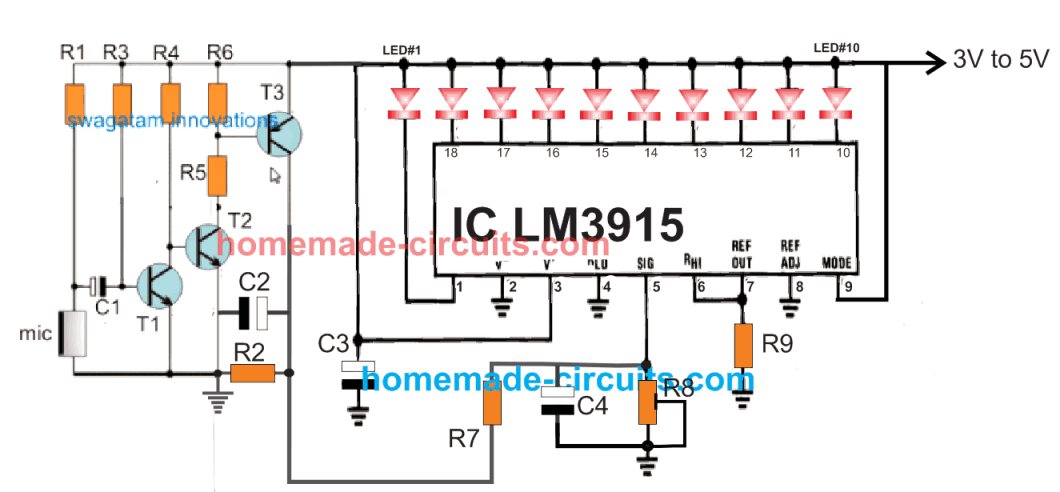
The circuit is basically built around two stages: 1) a microphone amplifier, 2) a LM3915 based digital LED display processor.
The T1, T2, T3 forms a simple transistorized mic amplifier circuit, which amplifies weak atmospheric music or audio levels to relatively stronger voltage amplitudes at the collector of T3.
The LM3915 is configured as a voltage detector and an LED driver. Any voltage rise and fall pattern at its pin#5 is transformed into a correspondingly sequencing 10 LED display bar graph display connected across the 10 outputs of the IC.
Meaning, at the minimum voltage range, LED#1 will illuminate and as the voltage rises, the corresponding LEDs will begin illuminating in an incrementing sequential manner. At the maximum range the 10th LED will illuminate.
The process will reverse as the voltage drops at this pin, creating a continuous to and fro movement on the LED illumination witha wonderful music enriched light effect.
This maximum detection range can be set or adjusted with the shown 10K preset attached on the same pinout of the IC.
In the proposed design, the amplified audio output from the MIC stage is applied to pin#5 of LM3915. The IC sense the varying amplitudes of the music signals and accordingly causes the LEDs to dance in the intended reverse forward pattern.
The values of C2 and R2 together for individually could be tweaked for adjusting the time response of the sequencing. Higher values will allow slower movement of the LEDs, while lower values will allow the LEDs to sequence at a faster rate.
Video Demonstration:
Parts List
- R1 = 4k7
- R2, R6, R9 = 1K
- R3 = 2M2
- R4 = 33K
- R5 = 470 ohms
- R7 = 10K
- R8 = 10k preset
- C1 = 0.22uF ceramic
- C2 = 100uF/16V or 25V
- C3, C4 = 1uF/16V or 25V
- T1, T2 = BC547
- T3 = BC557
- MIC = electret MIC
- LEDs = all are red LEDs, 5mm, 20mA type, or as desired.
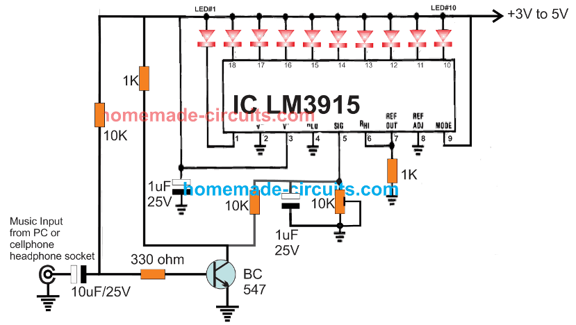
How to Connect with a 3.5mm jack Audio Input
For users who do not wish to have a wireless music level detection functionality can easily modify the design accordingly by eliminating the MIC amplifier stage entirely.
The schematic for a 10 LED music level indcicator for USB connection or for a 3.5mm mobile phone connection is shown below. The circuit input can be also be directly connected with a loudspeaker terminals for achieving the required high quality music level indication.


Questions & Answers
Hi Swagatam, I have a Chinese music chip that will play several English melodies and it will light two different LEDs. One LED flashes to one tone and the other LED will flash to a different tone. It is very interesting as the two LEDs flash to different beats of the music. I am wondering if you might be able to replicate this LED action with a simple circuit. Thanks!!!
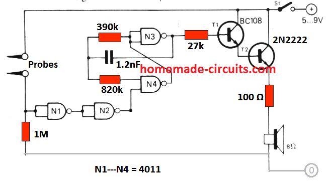
Hi Norman, I think the following 555 monostable could be used to replicate the LED action. The 1000uF capacitor could be reduced to 0.1uF or some other suitable value. The output pin#3 can be connected to an LED. The trigger point could be connected with the music input:
Hello,
Is there any other replacement for c1-0.22uf ceramic? Having trouble locating one from the plethora of circuit boards I have on hand here at my house. Thank you, James. P.S. love the articles on diy electronic projects that you share.
Hello James, I think any capacitor between 0.1uF and 1uF should work for C1. Glad you liked the articles, thanks for the feedback!
Hi, I would like to join your company Mr.Swagatam
Sure, you are most welcome!
Good afternoon .
I am a student of one university and I chose your scheme for my term paper. At one point, I need to simulate the operation of this circuit and take measurements, but this circuit does not work in the Multisim application. Instead of a microphone, I used an AC power source. If you connect the source directly to pin 5, then the circuit works, then the problem is in the amplifier. What do you think might not work and how to fix it?
Thank you in advance
Thank you selecting this circuit for your term paper. However I have no idea why the circuit might not be working in multisim, it’s probably a multisim problem, not the circuit problem, so it is difficult to judge.
With reference to my question posted on the page Automatic LED Candle Light Circuit: ” Hi, I have had an idea of music driven LEDs wirelessly which seems to be very complex to me. Let me try to make the problem understandable.
I want a music activated led driver but without a mic as the audio input to the driver. I want to stream the music to my Bluetooth speakers/headphones meanwhile the LEDs reacting to the music as they would have with the mic.
Basically I want to play loud music with the light effects without bothering my neighbors. I know how to build the circuit using Arduino, mic being the source to the driver. I have been looking for a solution to drive it wirelessly as I explained above for months now but I couldn’t get to a solution.
I hope I have made you understand the problem, kindly help me to build this project. If you need any clarification please get in touch with me. I hope you find this project exciting and provide me enough input so that I could build it.” Please go through this video for reference:
youtube.comxxxxxx
I wish to develop something similar to this with some changes as: a) I don’t want to use the microphone as the receiver to the driver.
Rather I would like to put some interface that would receive the audio signal being played on my phone/computer directly to the driver (either Wi-Fi or Bluetooth or any other communication interface that would help it), then the driver circuit would illuminate the LEDs according to the strength of the audio signal received. b) with this I simultaneously want to be able to play the music over Bluetooth on my headphones too.
I basically want to play the music without the use of microphone to avoid the conflict that would come with playing loud music.
I hope I have been able to put my problem in proper words.
I am an electrical engineer and I have started designing power electronic circuits for 4 months now and this project kind of had my attention for almost 2 years now when I had started with my masters but couldn’t do it due to academic constraints.
I have made researches trying to find a way to do it but I couldn’t get anything on it. I hope you would try helping me out with this and probably come up with some forward way. Thanks, Arjun
Removing the MIC is not a problem, since the input could be taken from any suitable source through wires. The problem is the creation of the LED pattern. From the video it seems the LEDs through the long LED strips are running or chasing from one end to the other, and the chasing speed is getting faster or slower depending on the volume or the pitch of the music.
Is this the effect you are looking for?
well not exactly the same pattern. I would just want the LEDs to respond to the music in such a way that the brightness of the LEDs is related to the loudness of the music. Though I think with some proper coding and debugging the pattern could be changed.
please go through this page: xxxx
I want something similar to this with the i/op port as discussed before.
On that note, what could be the alternative to mic as an input and it would be really helpful if you just guide me with some notes or materials that I could go through and understand it better.
Two things, first of all what you are showing through videos and the other links are hugely complex and will need special coding and softwares which I cannot do.
Secondly if you need only brightness control through music that’s extremely simple….. so the two applications are far from each other and not matching.
Either you have to select a super simple music dependent LED brightness circuit, or the highly complex randomly changing LED music lights.
So please clarify what is your exact need.
I built this following your circuit diagram and its not working at all. Why is that? It seems like IC LM3915 is not getting any signal input on pin 5 from the mic and its amplifier. LEDs are turning on only when I change the R8 preset position manually.
Check and confirm the sound MIC amplifier first…build the confirm the following circuit first, and then integrate it accordingly with the LM3915:
https://www.homemade-circuits.com/simplest-sound-activated-relay-switch/
Ok, I will try that, hope it works.
Can I use some other capacitor instead C1 (0.22 uF, ceramic)? Is ceramic capacitor only option or I can replace it with some other type?
You can use any type of capacitor for C1.
I am a hobbyist, thank you very much for the circuit of wireless VU meter. I made it on a breadboard and working absolutely perfect. I have earlier tried some circuit which did’nt work, thanks again.
I would like to know how can the sensitivity of the mic can be improved.
You can increase the sensitivity of the MIC by reducing R1 value or increasing C1 value
Thanks, it worked now I am using at C1 .47uf capacitor and at R1 18k resistor.
Glad you could increase its sensitivity as per the instructions.
Will try and come back to you, thanks.
Hi Swagtam
I am very new to circuit building and was wondering if you could possibly point me in the direction.
I have a project in mind and i want to know if it is even possible. Let alone if a newbie like me should even try and attempt to do something like this.
If i can somehow talk to you privately please leave a reply.
Thank you
Jake
Hello Jake, I appreciate your interest, and I would be happy to help. However it would be great if you could discuss it here through comments, I’ll try my best to solve it.
Can we control the sound input with a potentiometer so that it can act as a sound trigger. If sound exceeds certain level it can trigger a ckt?
Pls reply sir
Hi Adithyaraj, you can do it by connecting a pot in series with R1, or R6
Sir can you modify this circuit for 230v ac lamps.so that it works as dj light.
You can do it in this way.
Connect BC557 transistor base across all the outputs of the IC through individual 1K resistors. Connect their emitters with the positive line. Connect their collectors with individual triac gates, connect the triac MT2 with the ground line. Configure the lamps with the triac MT1 and AC mains. However this will make the entire circuit float with AC mains 220V so be extremely careful while testing it.
Then please help to make an circuit of wireless display of weighing scale with aurdino
Thank you very much
Sorry Manju, I am still not good with Arduino, so it can be difficult for me to code this!!
SIR I NEED WIRELESS DISPLAY FOR ELECTRONIC WEIGHING SCALE DOES IT POSSIBLE TO CONSTRUCT WITHOUT AURDINO
Hello Manju, without Arduino it may be impossible to make this project.