In this post I have explained a simple circuit using Passive Infrared or PIR for making an automatic solar LED lamp which can be used for illuminating your home automatically at sunset, and only in the presence of a human member in the premise.
By SS Kopparthy
Introduction
Here, in this article, I will discuss a simple yet useful and improved version of the PIR based automatic home lighting system. A previous version of this circuit is already discussed and is available here: https://www.homemade-circuits.com/pir-motion-activated-relay-circuit/ The major improvement is the static detection of human beings and also it works completely on solar energy unless the battery doesn’t get charged on a rainy day or something.
Circuit Working:
The circuit consists of different stages, where each one performs a specific task to keep the circuit working. The first one is the solar panel, solar charge controller and the battery which together control solar based power supply to the circuit. The same stage decides whether power is to be fed from the battery or from the mains, depending on the battery charge and voltage.
Circuit Diagram
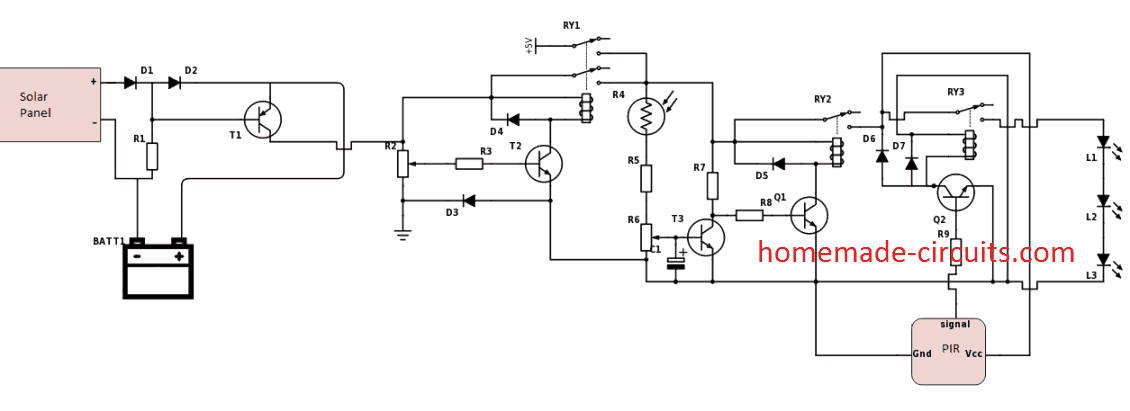
A 8550 PNP transistor is used here in the solar charge controller to decide it is day or night depending on the voltage form the solar panel. This is achieved by feeding the solar panel voltage to the base of the transistor hence holding it off during the day time when the voltage is produces by panel. When the dusk sets in the voltage drops across the transistor and battery voltage gets routed to rest of the circuit.
The next stage is a voltage source switcher that decides whether the circuit should be powered using battery voltage or the AC power source depending on the battery voltage level. A DPDT relay is configured to take care of this switching. Hence, the power to the circuit remains uninterrupted.
The next stage consists of the day/night detector that senses whether it is day or night depending on the sunlight incident on the LDR and it triggers the relay correspondingly. A capacitor C1 is attached at base of the transistor T3 in this stage. That makes sure that a small delay is introduced in the sensing so that sudden changes in the intensity of light does not false trigger the circuit. Output of T3 is fed to the next transistor Q1 which actually triggers the relay.
Final stage consists of a PIR sensor HC-SR501 that produces a high output when it detects the presence of a human being in its vicinity which is fed to the base of the transistor Q2 and immediately it fires the relay and the LED’s connected to it gets lit up. When the human moves away, the light gets turned off automatically using the same mechanism.
Finally, for the circuit to work even when there is static occupancy, the an additional stage consisting of the Hex Schmitt trigger IC and few other components may be used in combination with the existing circuit, but please remember to use a bigger battery and solar panel as per requirement. The circuit can be found here: https://www.homemade-circuits.com/pir-circuit-for-detecting-static-or/
List of Components:
Solar panel- 10.2V,400mA, 6Watts,
BATT1- 6V, 4.5Ah battery
R1- 1K
D1, D2, D3, D5, D6- 1N4007
D4, D7- 1N4148
R2- 10K trimpot
R3- 200E
R4- LDR
R5, R8, R9- 1K
R6- 10K preset
R7- 10K
T1- 8050
T2, T3, Q1, Q2- BC547
C1- 10
RY1- 5V, DPDT relay
RY2, RY3- 5V, SPDT relay
L1, L2, L3- LED's
PIR- HC-SR501
Notes:
After completion of this automatic PIR based solar home lighting circuit assembly, the unit can be housed inside a suitable casing(plastic) and installed the in a safe position protected from weather. The solar panel, LDR needs to be located such that sunlight is incident on them directly.
Here is the video of my prototype showing the static occupancy detection, please note that solar panel is not connected to the circuit in the video as the circuit is indoor and also the circuit for PIR sensor motion is powered externally for the time being.
A Simplified Design can been seen below:
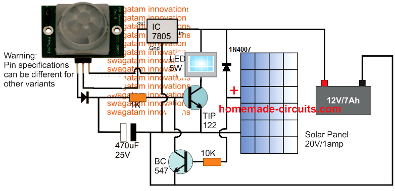
PIR Solar LED Home Lighting Circuit made Simpler
In this next concept I have explained yet another simpler version of a PIR based solar home lighting circuit which will provide the user with the following useful features:
1) It will charge a battery during daytime through a solar panel while sunlight is available.
2) As soon as darkness sets in, the circuit will automatically switch ON a connected LED lamp using the charged battery power, but only in the presence of a human being within the range of the PIR device.
That means, the circuit will not only switch ON an your home LED lamp automatically during evening, but also ensure that the lamp is not always switched ON, rather switch ON only when a person enters the detection range of the circuit.
How the Circuit Works
Now let's understand the circuit description with the following points with reference to the above diagram:
The circuit has three main stages: The first stage comprises of the PIR based LED driver circuit which is designed to detect a human being within a stipulated range and switch ON the attached LED lamp.
The second stage is formed by the Solar panel based battery charger circuit, through a 7-8-1-5 IC based voltage regulator stage.
During daytime the solar panel supplies around 18 Volts to the 7-8-1-5 IC, which is stepped down to a regulated 15 DC output.
This 15 Volts output DC is further reduced to around 13.8 Volts DC through the two series 1N5402 diodes.
This 13.8 Volts is then finally applied to a 12 Volts / 7 A-h lead acid battery so that it begins charging.
Since the maximum DC voltage to the battery is restricted to around 13.8 Volts, there isn't any danger of the battery getting overcharged, which means that the battery does not require an auto cut-off circuitry, regardless of how long it remains connected with the solar panel output.
The design also employs a feedback stage which makes sure that the LED lamp is not able to switch ON as long as the solar panel is generating a voltage, or in simple terms as long as it is not significantly dark outside.
The above feature is implemented using the BC 5-4-7 transistor, which remains turned ON as long as a voltage is available from the solar panel, and during this period it keeps effectively keeps the base of the LED driver transistor T-I-P 1-2-2 grounded, rendering it switched OFF.
With the T-I-P 1-2-2 transistor turned OFF the lamp lamp also remains turned OFF during the daytime.
Once significantly dark, the solar panel stops generating any voltage causing the BC 5-4-7 transistor to switch OFF, instantly enabling the T-I-P 1-2-2 transistor, so that it can now conduct and switch ON the LED lamp.
However, the T-I-P 1-2-2 transistor still requires a base voltage from the PIR device output to turn ON the LED lamp, and this base voltage from the PIR device is not achieved unless and until an actual human presence is detected in the vicinity.
Therefore, the circuit keeps the LED lamp turned OFF even in the evening, until a human being is detected within the PIR range, which saves precious battery power and allows the LED lamp to be illuminated throughout the night, whenever the user actually needs the premise to be illuminated.
So, that's it folks! This concludes our explanation on the solar powered automatic LED lamp circuit using PIR detection, if you have any related questions, you know what to do...yes, just use the comment box below to jot in your doubts.


Questions & Answers
hello sir,
sir can i used bd139 instead of tip122? i will use 12 volt 2500mah batery and 12 volt 5 watt mini solar….
Thanks Ghulam,

You can use BD139 but the maximum current handling capacity cannot be exceeded above 500 mA or 1 amp at the most.
12V solar panel cannot charge a 12V battery, you will need an 18V solar panel.
And for better performance please add a 220 ohm resistor in series between the 7805 output and PIR +input.
You can also consider using the following simple design:
yes its working. thank you sir……
That’s great Ghulam, let me know if you have any further issues with the circuit…
thank you sir, i will update you if i face any problem.
No problem Ghulam! Let me know how it goes….
sir PIR can work on 12v?
PIR will not work with 12V directly, it requires 5V to work, but in the last circuit above the PIR VCC is connected with a series 1k resistor, so with this series 1k it can be used with 12V DC. I have tested it…
i am sorry for disturb you for one project, sir i dont have 5402 diode, can i use 5408 or in4007 plz?
Yes, 1N5408 will work, no problems.
Hi, I’m Agnes, how can I get the full project?
Hi, can you please specify your full project specifications.
As I am having a solar panel 3W 6V solar want to make a circuit board diagram dc to dc can u please explain which of the products are there as I am using 3.7v battery 18650.As it is to used for a passage
I could not understand your requirement, please explain it elaborately.
Hello Mr. Swagatam I hope you are well, I am very pleased with you. The information sharing you have shared is very valuable to me, so I pray for you every day. I used to be an electronic device repairman, now I quit because I am 62 years old, some of my opportunities are limited and I am struggling for life due to my orthopedic disability. I have a request from you. I need a voltage detector diagram that determines the place where the electrical installation and water installation goes under 40 cm concrete. I would appreciate if you could help me. Thank you very much for your precious time.
Thank you Mr. Turan, I think you can try the following concept for detecting mains energy under concrete walls.
https://www.homemade-circuits.com/bug-detector-circuit-rf-sniffer-circuit/
For increasing the sensitivity of the circuit you an use longer wire for the antenna
Hi Swag,
The Diode at output of PIR module is not identified.
Is it any redular diode?
Best Regards.
Nelio
Hi Neiio, yes it can be a 1N4148 or 1n4007 diode, although this diode and the 470uF are not required, since the PIR already has an in-built delay circuitry
hello sir, I want to built a solar light with this requirement :
1. using 20 watt led light
2. auto on at dawn and off in the morning.
3.light on for at least for 12 hours.
4.lithium battery fully charge in 5/6 hours
5. built with battery overcharge and discharge protection.
tq for your time..
Hi Kenny, You can try this circuit
Hi Swag,
I want a circuit for a fan on/off switch (inductive load) for inverter, as the inductive loads have surge currents. My idea is to have a delay on switch which connect the fan (or any other inductive load) to the inverter after a delay of about 5/6 seconds. So that initial high current is bared by mains supply and after 5/6 seconds it is connected to inverter, spacifically solar inverter.
Please guide in this matter.
Anil
Hi Anil, you can use the following concept:
https://www.homemade-circuits.com/simple-refrigerator-protector-circuit/
Replace the Mains input with inverter input, and Refrigerator with Fan.
Sorry, you will need to modify the triac with a relay, and connect the relay with the fan such that initially it is connected with mains and then switches to inverter. here’s the relay circuit for the same:
Hello and congratulations for your great work.
I am looking for a booster circuit to replace a thief joule
with a 5v solar panel, 4xli-ion 3.7v batteries, and also advice.
thank you !!
Thank you dijirotech,
Joule thief is also a booster circuit? Please specify your exact technical specifications and also the solar panel amp rating, I will try to help!
Thank you for your reply.
Could you please add the functionality so the light remains dim until movement is detected, and gets bright when motion sensors is triggered.
You can try adding a 100K resistor or some other calculated high value resistor between TIP122 base and the positive line. It may do the job
Hello
Can I use 7ah battery and 30W solar panel with this circuit?
7805 IC dissipate too much current, can I use a switching regulator instead?
Thank you for your good work.
That looks OK to me, You can use the mentioned parameters with the above cone[pt!
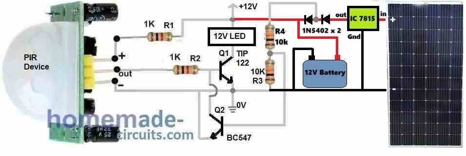
can you provide another circuit diagram ?
I have updated the diagram at the bottom of the post!
hi sir can make as the same circuit for 12v 7ah battery
Satish, you can usea 12V battery, but make sure to use a 7805 IC for supplying 5v to the PIR Vcc pin