In this post I have explained a single phase variable frequency drive circuit or a VFD circuit for controlling AC motor sped without affecting their operational specifications.
What is a VFD
Motors and other similar inductive loads specifically do not "like" operating with frequencies that might be not within their manufacturing specs, and tend to become a lot inefficient if forced to under such abnormal conditions.
For example a motor specified for operating with 60Hz may not be recommended to work with frequencies of 50 Hz or other ranges.
Doing so can produce undesirable results such as heating up of the motor, lower or higher than the required speeds and abnormally high consumption making things very inefficient and lower life degradation of the connected device.
However operating motors under different input frequency conditions often becomes a compulsion and under such situations a VFD or a variable frequency Drive circuit can become very handy.
A VFD is a device which allows the user to control the speed of an AC motor by adjusting the frequency and voltage of the input supply as per the motor specifications.
This also means that a VFD allows us to operate any AC motor through any available grid AC supply regardless of its voltage and frequency specs, by suitably customizing the VFD frequency and voltage as per the motor specifications.
This is normally done using the given control in the form of a variable knob scaled with different frequency calibration.
Making a VFD at home may sound to be a difficult proposition, however a look at the design suggested below shows that after all it's not so difficult to build this very useful device (designed by me).
How it Works
If you do not wish to read the whole explanation, then you can watch this video instead:
OK, so I have designed this simple, basic VFD controller circuit which can be used to control all types of 220V or 120V single phase AC motor, as per the desired specifications. Let's try to understand how the circuit is designed to work.
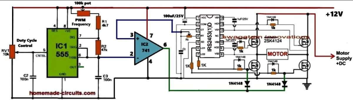
Referring to the above circuit diagram the proposed VFD circuit works in this way: The IC IRS2453 is configured as the basic full bridge or H-bridge inverter circuit which generates square wave output whose frequency is determined by the values of the Rt and Ct components of the circuit.
The output of this inverter is used to control the desired motor, whose speed need to be controlled as per the VFD rules.
In order to convert this square wave inverter into a sine wave VFD circuit, I have configured an adjustable SPWM generator stage using the IC 555 astable and an op-amp comparator.
The IC 555 is wired as a PWM astable circuit to generate the fast triangle waves as the carrier frequency which is fed to the non-inverting input of the comparator op-amp IC 741.
The slow triangle wave, which acts as the reference signal, is extracted from the Rt, Ct junction of the IRS2453 IC and is fed to the inverting pin #2 of the comparator IC 741.
The reference signal is intentionally derived from the Rt, Ct pin of the inverter IC to ensure that the SPWMs are perfectly synchronized with the set frequency of the inverter.
This frequency caan be set by adjusting the Rt resistor which can be a potentiometer.
The 741 IC compares the two input waveforms and generates an equuivaalent SPWM output waveform from its pin#6.
This output is integrated with the low side MOSFET gates of the H-bridge inverter IC so that the square wave operation of the inverter is transformed into an SPWM equivalent sine wave output.
Now, how does this basic sine wave inverter circuit turns into a variable frequency drive?
It is done by providing the adjustments for the frequency control and the RMS voltage control of the inverter output which controls the motor.
So with this sine wave inverter you can adjust the output RMS frequency by adjusting the duty cycle of the SPWM carrier wave and the frequency can be adjusted by adjusting the Rt resistor of the inverter IC which supplies the reference frequency for the SPWM.
How to Calculate Single Phase VFD Parameters
Input Power Calculations:
Power Factor (PF):
This is all about measuring how efficiently we are using AC power. It is extremely important for making sure we size the Variable Frequency Drive (VFD) correctly.
Apparent Power (S):
This represents the total power that’s supplied to the VFD, and it includes both real power and reactive power.
Formula: S = V * I
Real Power (P):
This is the actual power that the motor uses to do its work.
Formula: P = V * I * PF
Reactive Power (Q):
This is the power that bounces back and forth between the source and the load without doing any useful work.
Formula: Q = √(S² - P²)
Output Power Calculations:
Motor Power (Pmotor):
This refers to the mechanical power that comes out of the motor.
Formula: Pmotor = (Torque * Speed) / 9550 (for horsepower).
The constant 9550 is an important number we use in the formula that connects power, torque, and rotational speed when we’re working with the SI system of units.
Formula:
Power (kW) = Torque (Nm) * Speed (rpm) / 9550
What is its Importance
So, what is so important with the constant 9550? It comes from how we convert between different units of power (in kilowatts), torque (in Newton-meters), and rotational speed (in revolutions per minute). This number helps us to tackle the differences in these units, making sure that our equation works correctly.
- Power is measured in watts (W) or kilowatts (kW).
- Torque is measured in Newton-meters (Nm).
- Rotational speed is measured in revolutions per minute (rpm).
To get to that constant 9550, we need to think about a few things:
- Converting power from kW to W.
- Changing rotational speed from rpm to radians per second.
- Using the relationship that says power equals torque times angular velocity (power = torque * angular velocity).
When we do these conversions and simplify everything, we end up with that handy constant 9550 in our formula.
Remember:
This formula is specifically designed for the SI unit system. If you happen to be using different units, for example like horsepower or foot-pounds, then you will need to use a different conversion factor to make it work.
Motor Efficiency (η):
This is a measure of how well the motor converts input power into output power.
Formula: η = Pmotor / Pinput
VFD Sizing:
VFD Power Rating:
The power rating of the VFD needs to be higher than the apparent power of the motor's, so that it can handle any potential overloads without an issue.
Input Current:
We can calculate the input current based on the VFD's power rating and the input voltage specifications.
Output Current:
We also need to figure out the output current based on the power rating of the motor and output voltage.
Motor Speed Control:
Motor Speed (N):
The speed of an induction motor is directly connected to the frequency of the voltage we apply.
Formula: N = (120 * f) / P (where f is frequency and P is the number of poles)

I want more items to share
Can I use 220 volt single phase vfd to convert my normal one ton ac compressor to multi speed compressor and control with temperature sensor . If so please help me to design economical circuit for same 220 volt ac compressor.
Mostly yes, single phase VFD can be used with AC compressor, but only if the motor of the compressor is not a capacitor-start type. However, using temperature sensors you can directly control the AC compressor output without a VFD.
Hi,
I have a bench drill Cthat will not go slower than 450 rpm approximately. I want to drill large diameter stainless steel holes and at that speed the bits burn out. Other than getting special expensive bits I think it may be a reasonable option to use less than 50 Hz input for the 700 watt single phase motor. I am thinking something around 5 to 10 Hz range. Can you advise and are there plans that you can supply for the project.
Cheers.
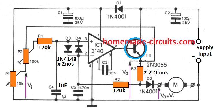
Hi, I won’t recommend reducing the frequency, instead you can use a back emf based dimmer circuit as explained in the following post:
https://www.homemade-circuits.com/how-to-make-versatile-closed-loop/
Hi
220V AC of main voltage increasing to 310V DC after rectifying by Diode & capacitor
i have question , with 310V how to control 220v motor ?
Hi, the SPWM chopping from the 741 output across low side MOSFET gates will reduce the voltage to 220V or lower.
Hello Sir, how do I control the full H-bridge( with 2110) using Arduino in terms of code and connection?
Hello Everisto, you can use the following Arduino code and integrate it with your 2110 IC for implementing an H-bridge inverter:
https://www.homemade-circuits.com/simple-arduino-sine-wave-inverter/
I wish you did a demonstration of a single-phase project in Multisim using P type and N type Mosfets