In this post I have explained a single phase variable frequency drive circuit or a VFD circuit for controlling AC motor sped without affecting their operational specifications.
What is a VFD
Motors and other similar inductive loads specifically do not "like" operating with frequencies that might be not within their manufacturing specs, and tend to become a lot inefficient if forced to under such abnormal conditions.
For example a motor specified for operating with 60Hz may not be recommended to work with frequencies of 50 Hz or other ranges.
Doing so can produce undesirable results such as heating up of the motor, lower or higher than the required speeds and abnormally high consumption making things very inefficient and lower life degradation of the connected device.
However operating motors under different input frequency conditions often becomes a compulsion and under such situations a VFD or a variable frequency Drive circuit can become very handy.
A VFD is a device which allows the user to control the speed of an AC motor by adjusting the frequency and voltage of the input supply as per the motor specifications.
This also means that a VFD allows us to operate any AC motor through any available grid AC supply regardless of its voltage and frequency specs, by suitably customizing the VFD frequency and voltage as per the motor specifications.
This is normally done using the given control in the form of a variable knob scaled with different frequency calibration.
Making a VFD at home may sound to be a difficult proposition, however a look at the design suggested below shows that after all it's not so difficult to build this very useful device (designed by me).
How it Works
If you do not wish to read the whole explanation, then you can watch this video instead:
OK, so I have designed this simple, basic VFD controller circuit which can be used to control all types of 220V or 120V single phase AC motor, as per the desired specifications. Let's try to understand how the circuit is designed to work.
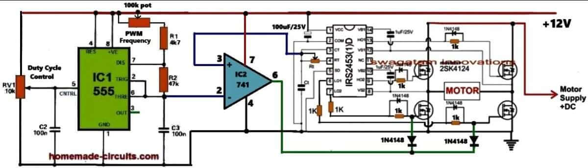
Referring to the above circuit diagram the proposed VFD circuit works in this way: The IC IRS2453 is configured as the basic full bridge or H-bridge inverter circuit which generates square wave output whose frequency is determined by the values of the Rt and Ct components of the circuit.
The output of this inverter is used to control the desired motor, whose speed need to be controlled as per the VFD rules.
In order to convert this square wave inverter into a sine wave VFD circuit, I have configured an adjustable SPWM generator stage using the IC 555 astable and an op-amp comparator.
The IC 555 is wired as a PWM astable circuit to generate the fast triangle waves as the carrier frequency which is fed to the non-inverting input of the comparator op-amp IC 741.
The slow triangle wave, which acts as the reference signal, is extracted from the Rt, Ct junction of the IRS2453 IC and is fed to the inverting pin #2 of the comparator IC 741.
The reference signal is intentionally derived from the Rt, Ct pin of the inverter IC to ensure that the SPWMs are perfectly synchronized with the set frequency of the inverter.
This frequency caan be set by adjusting the Rt resistor which can be a potentiometer.
The 741 IC compares the two input waveforms and generates an equuivaalent SPWM output waveform from its pin#6.
This output is integrated with the low side MOSFET gates of the H-bridge inverter IC so that the square wave operation of the inverter is transformed into an SPWM equivalent sine wave output.
Now, how does this basic sine wave inverter circuit turns into a variable frequency drive?
It is done by providing the adjustments for the frequency control and the RMS voltage control of the inverter output which controls the motor.
So with this sine wave inverter you can adjust the output RMS frequency by adjusting the duty cycle of the SPWM carrier wave and the frequency can be adjusted by adjusting the Rt resistor of the inverter IC which supplies the reference frequency for the SPWM.
How to Calculate Single Phase VFD Parameters
Input Power Calculations:
Power Factor (PF):
This is all about measuring how efficiently we are using AC power. It is extremely important for making sure we size the Variable Frequency Drive (VFD) correctly.
Apparent Power (S):
This represents the total power that’s supplied to the VFD, and it includes both real power and reactive power.
Formula: S = V * I
Real Power (P):
This is the actual power that the motor uses to do its work.
Formula: P = V * I * PF
Reactive Power (Q):
This is the power that bounces back and forth between the source and the load without doing any useful work.
Formula: Q = √(S² - P²)
Output Power Calculations:
Motor Power (Pmotor):
This refers to the mechanical power that comes out of the motor.
Formula: Pmotor = (Torque * Speed) / 9550 (for horsepower).
The constant 9550 is an important number we use in the formula that connects power, torque, and rotational speed when we’re working with the SI system of units.
Formula:
Power (kW) = Torque (Nm) * Speed (rpm) / 9550
What is its Importance
So, what is so important with the constant 9550? It comes from how we convert between different units of power (in kilowatts), torque (in Newton-meters), and rotational speed (in revolutions per minute). This number helps us to tackle the differences in these units, making sure that our equation works correctly.
- Power is measured in watts (W) or kilowatts (kW).
- Torque is measured in Newton-meters (Nm).
- Rotational speed is measured in revolutions per minute (rpm).
To get to that constant 9550, we need to think about a few things:
- Converting power from kW to W.
- Changing rotational speed from rpm to radians per second.
- Using the relationship that says power equals torque times angular velocity (power = torque * angular velocity).
When we do these conversions and simplify everything, we end up with that handy constant 9550 in our formula.
Remember:
This formula is specifically designed for the SI unit system. If you happen to be using different units, for example like horsepower or foot-pounds, then you will need to use a different conversion factor to make it work.
Motor Efficiency (η):
This is a measure of how well the motor converts input power into output power.
Formula: η = Pmotor / Pinput
VFD Sizing:
VFD Power Rating:
The power rating of the VFD needs to be higher than the apparent power of the motor's, so that it can handle any potential overloads without an issue.
Input Current:
We can calculate the input current based on the VFD's power rating and the input voltage specifications.
Output Current:
We also need to figure out the output current based on the power rating of the motor and output voltage.
Motor Speed Control:
Motor Speed (N):
The speed of an induction motor is directly connected to the frequency of the voltage we apply.
Formula: N = (120 * f) / P (where f is frequency and P is the number of poles)


Questions & Answers
Hey, i have a few questions, is the resistor next to the ic4017 a 1kOhm too, and which ranges should Cx be, and also is it possible to run this setup with dc input only, cause i would like to power a RC-car running with an asynchronous single phase motor.
Hi,
The pin14 resistor of the IC4017 could be a 100k.
for a DC motor you wouldn't require such a complex design since DC motors are not frequency dependent.
If you are looking for a PWM speed controller circuit, you could probably try the one given in the following link:
https://www.homemade-circuits.com/2012/05/make-this-pwm-based-dc-motor-speed.html
No i want to use the AC motor for my project, thats why i was looking for a self-built VFD, but without variable Cx it not be suitable for my project. And do you want to have the rectified AC from the transformator on pin5 at ic555 no.2 or could it be dc aswell?
VFD stands for variable frequency drive, meaning the frequency should be variable as per the motor requirement, you could make Cx fixed and use R1 as a variable resistor for the same, if the frequency is not variable the purpose of the circuit would become meaningless.
the input is taken from a 100Hz bridge source to make the AC mains input cycles synchronized with the circuits PWM output cycles.
Hi,
how to use the Arduino (as a PWM generator). It must also be insulated phase (eg. Optocouplers). What do you think? How to realize this?
With respect Evaldas
Hi, I am more used to with discrete electronics, can't say much about about Arduino stuffs.
ok, forget the Arduino. I will use optocouplers HCPL-314J. I want to know what the PWM frequency?
PWM frequency can be such that chops each square wave into 4 blocks, multiply the basic frequency with 4 or 5, that will give you the PWM frequency.
Please tell me what are the mosfets we can use for this project?
It will depend on the power requirement specs of the load…
What I shoud to conect to HIN, SD, LIN
connect them with the outputs of the second diagram.
Hello Swagatam…
Have you tested this circuit? What kind of motor have you tested? With which motor voltage? Did have the motor capacitor? Did the motor heat to much? The control of spinning was quite linear…? Sorry for too many questions, but I intent to build it with Microcontroller in the control part, for a Fan… If it works , i could share with your website…
Hello Julio,
I have not tested it yet, but everything looks correct to me in the design… you are welcome to share your design here, I'll publish it with your credentials
Julio, I also want to use it to control the fan motor. I'm more interested in controler (AVR) use. Could be used and the temperature feedback to prevent damage to the motor. For this case, use only the power control scheme. There remains a number of issues:
– What should be the PWM frequency? Low frequency noise is larger, poorer control, excessive frequency may cause heating of the parts, as well as might not be able to close the transistors and the scheme shall be burned.
– Galvanic isolation and would preferably otherwise remains electrical injury.
How are you maintaining volts per hertz relationship in circuit?
it will need to be set manually by adjusting the 180k pot and the voltage across the mosfets.
But as per my information, VFD's basic work is to automatically maintain V/Hz ratio to keep constant current but variable speed to the load…!
the word "variable" suggests that it has to be done manually, so in the above diagram also it's manual not automatic.
Igbt number?
Can i sent my observation to u?
I used this ckt.
sure you can send it.
mosfets could be IRF840
I'm going to build this circuit but I'm wondering what cx do I use?
you can use 0.1uF and adjust the adjoining 180k pot for refining it to the required levels
I drew one single circuit (connected 2 circuits together) and I'd like you to confirm that all is correct in it, if possible.
I cant post images in the comments.
you can send it to my email which is given in the "contact" page, or upload to any free image hosting site and provide the link here.
oi59.tinypic.com/2ai1mcn.jpg
pin5 of IC2 should be connected to an AC source, for example a 100Hz ripple from the a bridge rectifier.
This is for setting the amplitude of the PWMs in accordance with the mains AC value.
However this can set using a 1K pot also.
remove the pin5 (IC2) link entirely.
take a 1K pot and connect its center pin to pin5 of IC2, the other two outer pins should be connected to positive and negative of the supply respectively.
Thank you Swagatam Majumdar for your help. I appreciate it.
I hope now all is correct. i61.tinypic.com/2nkj6le.jpg
What about resistor wattage and c11 capacitor? Am I right about them?
It looks perfect to me now.
All resistors are 1/4 watt……C11 could be an electrolytic, or 10nos of 1uF/1KV (MKT)connected in parallel
….yes two 20mfd/450V in series could also be tried for C11
R14/15 can be also 0.25watt rated…no issues.
Thank you Swagatam Majumdar!
I hope I'll try it in february.
this circuit is not working……can anyone help me to understand working of all major components in this circuit….plz
Please specify the type of motor to be used. May I use a split phase capacitor start fan motor? And also specify the frequency range of first IC for satisfactory operation of this project. I am doing this circuit as a project for my students and have to design the transformer based on your reply.Please reply.
I have no idea which motors typically require an VFD, I have only tried to present a suitable circuit based on the studied concept
the frequency range can be between 10 and 500 Hz if 1uF is selected for Cx
Dear sir please provide me any circuit for solar 500-600 vdc (9amp) to 220 ac
Dear Ups, can you provide some more details about the application and the requirement, it will help me to design the circuit in a better way.
dear sir i am getting problem in half bridge driver circuit part in this circuit…control part is working well….can u make me understand hoe this part is working…
dear anshdeep, the input HIN and LIN should be connected to the 4017 outputs, thus when HIN is high, LIN should be low and vice versa, as long as this is happening the output of the IC will switch the mosfets and the connected load….the shut down pin is not relevant and may be kept open.
alternatively you can simply eliminate the entire 4017 stage and the half bridge, and connect a mosfet directly with the pin3 of IC and drive the motor through it.
Hi Sir.., my project is upon Single phase Induction motor of 60W,230V,0.28A rated…My query in this circuit is that at the Inverter output terminal is that possible to achieve 230V ac with 12V battery as input. or I supposed to put step-up transformer..
Hi Hemanth, if you apply 230V at the mosfet drain side then the output will be optimized for 230V, so basically the output will depend on what input is fed to the drain side of the upper fet.
Hello Swagatam, nice project you have here. I just started to make the components list and pcb to order so i can build your VFD,it's perfect for my 250W ac single phase motor. Thank you for sharing the project :). I have some questions if you dont mind. In the first picture we have an IC IR2110 and the drain side of the mosfet goes to an electrolytic 10uf/1KV capacitor and to: Up to 500v or 600v, but in the third picture the drain side of the mosfet goes only to the electrolytic capacitor . so the question is how the ac single phase motor powered? and where we have ac or dc because its a little confusing,the up to 500v or 600v is ac or dc ?. Many thanks!
thanks mtn, in the last diagram the drain of the high mosfet needs to be connected to the desired high voltage DC bus source,,,yes it's not shown in the diagram, if possible I'll tru to update it accordingly soon.
please note that the design is a manual VFD so the V and Hz will need to adjusted manually through the indicated pots.
Waw… 600V DC input,that is something… It will be hard to reach such volts. If i recify a 220V AC supply with filter capacitors it will reach 310V DC,is that enough to power my 1A 220v AC single phase motor? i know we have a potentiometer for V and Hz but how it works? if i have 310V DC supply i can change the output voltage from 0 to 310V AC to power the motor? And on top of that i have problems with the parts list, i have to buy equivalents for the IC's. I have CD4017BM SMD for the decade counter/divider, IR2110PBF for mosfet driver and SA555N for astable/monostable timer. I can buy only from TME. Thinking they are fine withs specifications,what do you think? Ooh,and thanks for the reply 🙂
600V won't be required if you intend to control a 220V motor…yes 310V would be just right for your application, and you would be able to adjust the RMS right from 0 to 310V
The numbers of the parts you have mentioned are all OK according to me, and should work as specified.
…but please be warned….this project is not for the noobs, it's only for the hardcore experts :-]
Let's say i'm not an hardcore expert,but for my level,this project looks fine to do,still it's a demanding one…My weakest point is to understand how the circuit works,how the IC's works and how to combine them to make a magic output ;P. Got all those fancy terminologies in the description that drive me crazy, but i have years to learn. For now i just follow the diagrams,make the pcb's,solder everything and make them work,one day i will learn the theory behind the hardcore circuits that i encountered. Just got the information that my K2837's can't arrive,so i'll use FDA50N50 for the power MOSFET's,they have low Rds=89mO, Vds=500V, Vgs=+-20v and Id=48A,they must also be fine. As soon as i finish the PCB in Sprint Layout i will post some images for the others too see it,an image with the updated schematic from Mr. Vuleek Unteeluv with the 310v DC input correction and upload the .LAY file of PCB for the others to use it. Thanks :).
There are too many things to be learned and digested in the shown design, one explanation could need a subsequent explanation to be understood and the strings of such explanations can be quite long.
however If you are confident then you must go ahead.
The mosfets are not so critical, it just needs to be matched with the load specs for preventing it from heating up too much.
certainly, would love to see the images:)
wish you the best!
I'm back, finished at last the PCB in sprint layout and i uploaded everything to DropBox https://app.box.com/s/yzlqg67ei0y8o6nulic19aj56in3leu3 with the updated schematic, .LAY file and everything that i found to be useful for me. I double-checked the PCB to be sure and in 2-4 days will arrive to me,so i can start soldering. Hope i didn't missed something, i have nightmares when random components start to heat with no reason… i'll make an update when i finish and test the PCB 🙂
thanks mtn, I wish you all the best!!
Hello 🙂 i'm back.. 1 month has passed since i posted. Couldn't work on the project because school started,had some exams at another course,and i had driving license exam..soo i didn't had much time to spend on the project. I worked on my PCB these days,and there are good news and bad news. The bad news are that i missed something,and some components heated up. I solved the problem but my circuit has no output. I tried to ask some help ,found that i had my IC3 output was messed up and tried to fix the problem ,but then i found other things and so on… My worst nightmares. Tried to solve everything,and in this point my PCB has many jumpers and looks horrible but i have an output,with the Hz meter i read from (if i remember) 10 to 1100 Hz aprox. but if i connect a load it doesn't do notting. Forgot to mention,i rectified 220v ac with rectifier and caps. and i supplied the circuit with 310vDC to see if i have an output,and my AC output voltage varies from 0,9V to 2V but it's somehow instable(sometimes shakes from 1.8v to 2.1 by itself) And unfortunately,i dont have an osciloscope so i can't test if my 555's work fine,or if i have a stable 1kHz output. But the good news are that i won't stop untill i make this circuit work. And i have a good ammount of spare parts,so no problem. I learned something about the IC's from the datasheet's and i understand a little bit more how the circuit works. I focused on your 2 first images,the one with the 555's and the one with the mosfet driver,checked the datasheets,found some errors with my pcb desing,and in these days when i have some free time,i will change the PCB design ,make a circuit diagram and correct the errors,hope this time it will work. I'll update the DropBox link content as soon as i correct all the errors,but i really can't be sure if i will not miss something again,because i allways miss something…for now. Anyways, if you have some time to answer some questions please. For IC2 555 at pin 5 ,like in the second image, we can use the positive 100hz dc ripple(if i say it right) , and you suggested that we can use instead a 1KOhm potentiometer like in the final circuit diagram from Mr. Vuleek. But how a potentiometer can transform a 12v DC powersupply into 100hz ripple for the pin5 ? Have you tested the circuit if it works? Some good advices? Hope i didn't missed some word,because it's late and i'm a little tired. Really wish i could understand this circuits concept from the core,because as you warned,it is frustrating sometimes but it doesn't matter,eventually it will work. Thank's again 🙂