Very often we see that output coming from a microcontroller, oscillator, comparator, or PWM stage is just not strong enough for driving a power MOSFET directly, it gives signal, yes, but gate does not respond properly unless some decent current reaches there.
A MOSFET gate behaves like a small capacitor, so now unless that gate gets enough charging current and also enough discharge path, then switching stays slow, not sharp.
When the gate charges too slowly, then the MOSFET remains longer inside its linear region, and during that time it starts heating more than it should, which means power gets wasted and efficiency drops a bit, sometimes more, depending on load.
So to avoid that, we normally put one transistor driver stage in between, because direct signal line alone often does not handle gate properly.
Here we will see two simple MOSFET driver circuits, one uses two BD139 transistors, both NPN, and the other uses BD139 with BD140 in push-pull totem pole form.
Both improve gate drive strength, however the switching action is not the same, one behaves slower on one side, while the other pushes and pulls the gate more properly, so response becomes different.
Audio/Video Representation
First Circuit: Dual NPN BD139 MOSFET Driver
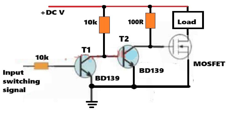
In the first design both transistors are BD139 NPN types and we first send the input switching signal through one 10k resistor into the base of transistor-1, which simply keeps the base current under limit, so the transistor does not get hit by too much drive current from the source.
The emitter of transistor-1 stays at ground but its collector goes upward through one 10k pull-up resistor to the positive supply, and that same collector point also goes straight to the base of transistor-2, so now transistor-1 is not only controlling transistor-2, it also flips the signal side,.
Now when the input goes high then transistor-1 turns ON and its collector drops almost near ground.
Since that collector point is also feeding transistor-2 base, then transistor-2 now sees low voltage there, so transistor-2 turns OFF.
Because transistor-2 collector is tied upward through another 100 ohm resistor, that point rises high, and this high level reaches the MOSFET gate, so now the MOSFET turns ON and the load starts working.
When input goes low then transistor-1 stops conducting, and its collector gets pulled high again by that 10k resistor.
That high then reaches transistor-2 base, so transistor-2 starts conducting and now its collector pulls the MOSFET gate downward toward ground.
So the MOSFET turns OFF and the load also goes inactive, simple as that, one transistor goes one side, the other follows opposite.
Important Characteristic of This Circuit
This arrangement already gives much stronger gate drive than direct logic output, because transistor-2 can push more current than the original signal source, so now the gate does not stay weak like before.
However the charging side and discharging side do not behave equal, that is where the difference comes.
Gate charging happens through a resistor, but gate discharge goes through transistor conduction, so discharge becomes faster while charging stays slower.
Since that difference is there, then this circuit fits better where switching speed is not very high, like low frequency switching, moderate PWM work, small inverter experiments and also relay replacement type circuits, where we do not need very sharp equal rise and fall every time.
Limitation
At higher switching frequencies, the gate charging path becomes relatively weak because the pull-up 100 ohm resistor limits current.
This causes slower turn-on and increases switching loss inside the MOSFET.
Second Circuit: Push-Pull Totem Pole Driver Using BD139 and BD140
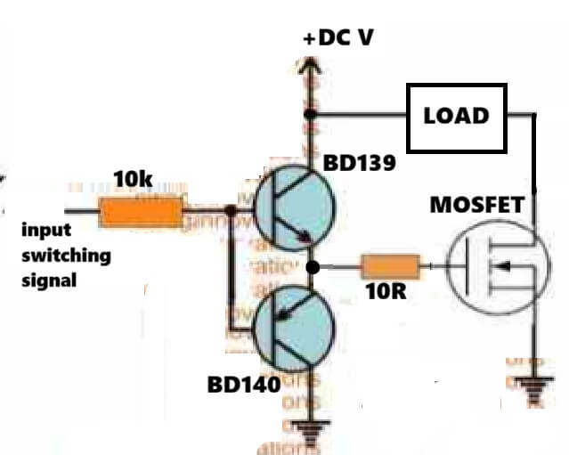
This second circuit is stronger, yep, because here both transistor sides work together, not one side only, so gate charging and gate discharge both happen better.
Here BD139 is the NPN transistor and BD140 is the PNP transistor, and we use both together which makes one push-pull stage, people also call it totem pole driver.
Now see the arrangement, input switching signal first comes through one 10k resistor, then reaches the common base point where both transistor bases join.
The collector of BD139 goes to positive supply, but the collector of BD140 goes to ground, so now both sides sit opposite and wait for input movement.
Their emitters are joined together and that common emitter point becomes the output line which is the working node from where drive comes out.
That output then goes to the MOSFET gate through 10 ohm resistor, so gate current gets controlled a little and sharp switching stays safer.
Why the 10 Ohm Gate Resistor Is Important
Even though this resistor is small, we still see it does an important job, because it positions there quietly but helps stop gate ringing, limits surge current during switching, protects the transistor pair from sudden current spikes, and moreover cuts unwanted oscillation which comes from gate wiring inductance.
How it Works
Now when input goes high, then BD139 turns ON and BD140 stays OFF.
So now BD139 pushes current into the MOSFET gate directly, which charges the gate fast, and because of that the MOSFET turns ON sharply and the load starts working without delay.
When input goes low then BD139 stops, and BD140 turns ON at that time.
BD140 then gives a quick discharge path from gate to ground, so the stored gate charge leaves fast, and therefore the MOSFET turns OFF sharply too.
The main useful thing here is that gate movement happens actively both ways, not only one side.
That means charging current is strong, and discharge current also stays strong, because both ON and OFF sides are forced by transistor action.
Since both transitions are tightly pushed, switching becomes faster and cleaner, which helps a lot when frequency rises.
So this kind of stage fits well for PWM work, inverter output side, high frequency switching, transformer driver sections, induction circuits, and also SMPS type designs, where clean gate control matters a lot.
Comparison Between the Two BJT MOSFET Driver Circuits
The first circuit is simpler, we can see that it uses only NPN transistors, so now building becomes easy, fewer parts, less trouble, and yep it works well where switching speed is not a big issue.
The second circuit however is stronger when gate movement must happen faster, because it does not only push current, but also pulls it back, so charging and discharging both happen harder.
In practical use, if switching frequency is low then the first one is often enough, no need to make things bigger than required.
But when PWM or inverter side runs faster, then the second circuit gives much better result, because gate transition becomes cleaner and quicker which helps overall switching.
Practical Transistor Selection
Although BD139 and BD140 are shown here, equivalent NPN and PNP transistor pairs can also be used.
If higher gate current is required, then stronger transistor pairs may be selected depending on the MOSFET gate charge.
Combining the Two MOSFET Drivers into a Single Hybrid Driver with Level Shifter
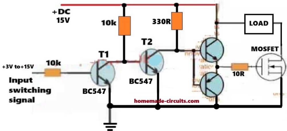
This hybrid MOSFET driver circuit operates as a high speed switching interface designed to translate low level logic signal into robust gate drive signals for a power MOSFET.
Now the circuit accepts an input switching signal ranging from +3V to +15V and operates on a main +15V DC supply.
It uses a sequence of bipolar transistors to buffer, level shift and push pull drive the gate capacitance of the MOSFET. When input signal goes high, then between +3V and +15V it turn on transistor T1 which pulls its collector voltage down near zero volts.
Because T1's collector is low, transistor T2 receives no base bias and remains turned off. With T2 off current flows from +15V supply through a 330 ohm resistor directly into bases of the complementary totem pole transistor pair.
This causes upper NPN transistor in totem pole to turn on while the lower PNP transistor turn off. Current then flows from upper transistor through a 10 ohm gate resistor to charge MOSFET gate capacitance up to approximately +14. 3V.
This turns the power MOSFET hard on into saturation, completing the circuit and activating load connected to +15V supply. Conversely when the input switching signal drop to 0V then transistor T1 turns off, allowing it collector voltage to be pulled high toward +15V through a 10k resistor.
This high voltage turns transistor T2 on which pulls the base of the totem pole pair down to zero volts.
As a result the upper NPN transistor turn off and lower PNP transistor turns on. The lower transistor create a low impedance path to ground, allowing charge stored in the MOSFET gate capacitance to drain away rapidly through the 10 ohm resistor.
This quick discharge brings the gate voltage below the threshold level cleanly and swiftly turning MOSFET off and cutting off current to load.
This hybrid design offer several key advantages.
Standard microcontrollers or logic ICs cannot source or sink high peak current required to charge and discharge power MOSFET gate capacitance quickly. The complementary totem pole buffer solves this by delivering high peak currents enabling fast switching transitions that minimize switching losses and prevent the MOSFET from overheating.
Additionally it acts as a level translator, allowing low voltage control source to effectively and safely drive power MOSFETs in full gate levels.

Questions & Answers
Thank you for your helpful website. I am going to try to use the Second Circuit: Push-Pull Totem Pole Driver Using BD139 and BD140. I would like to increase the output of a LM358 to drive a larger bank of Mosfets, the main circuit is a very simple slow comparator switch that maintains solar panels at their Voltage Maximum Power (Vmp) to feed a water heater element using large capacitors. I’m sure you would be interested in and would appreciate the circuit idea. I’ve only seen the circuit on Youtube where a guy has developed it and tested it successfully.
Thanks Eddy, glad you found the circuit useful. Using the BD139/BD140 push-pull totem pole driver is a great way to boost the LM358 output for driving a heavy MOSFET bank. Even though a solar Vmp comparator is relatively slow acting, having that extra current capability ensures the large gate capacitances are charged and discharged quickly without loading down the opamp or causing sluggish transitions. Feel free to share more details about that YouTube circuit or how your water heater setup performs. Please discuss it under the “solar water heater article”, from this blog…Cheers!
Dear Swagatam,
Thank you so much for your reply, really appreciated. Yes, the light came on and a + signal does turn the MOSFET on in both circuits. I’m trying to figure out a way to provide battery voltage (±12-15V) to the MOSFET gate. I stay on a farm, far from any major city and don’t have any logic level MOSFETS handy, and deliveries here are irregular and expensive. If I correctly understand the specs of the MOSFETS I have available, (VGS(th) 2V to 4V), the voltage range where MOSFET starts to conduct, but maybe not yet fully ON? The test conditions for RDS(on) is almost always quoted as 10V. And the maximum Gate-Source Voltage = ±20V. I reason that a car battery would fall in the safe range and turn a MOSFET fully on?
I don’t understand why the gate voltage will be 4.3V. In both your circuits, it looks like the MOSFET gate receives the DC Voltage through the 100Ω and 10Ω resistor and not from the input signal. I have this working and although the MOSFET gets hot, it works, sort of. I suspect that the MOSFET does not fully switch on with the 5V signal (and a long thin wire with a 200Ω gate resistor). Applying battery voltage directly to the fan it does appear to run faster. At the moment I’m using a IRF640N MOSFET and the 12V fan is rated at 50W. I also have many other MOSFET’S with higher amp ratings available.
Thank you Jacques,
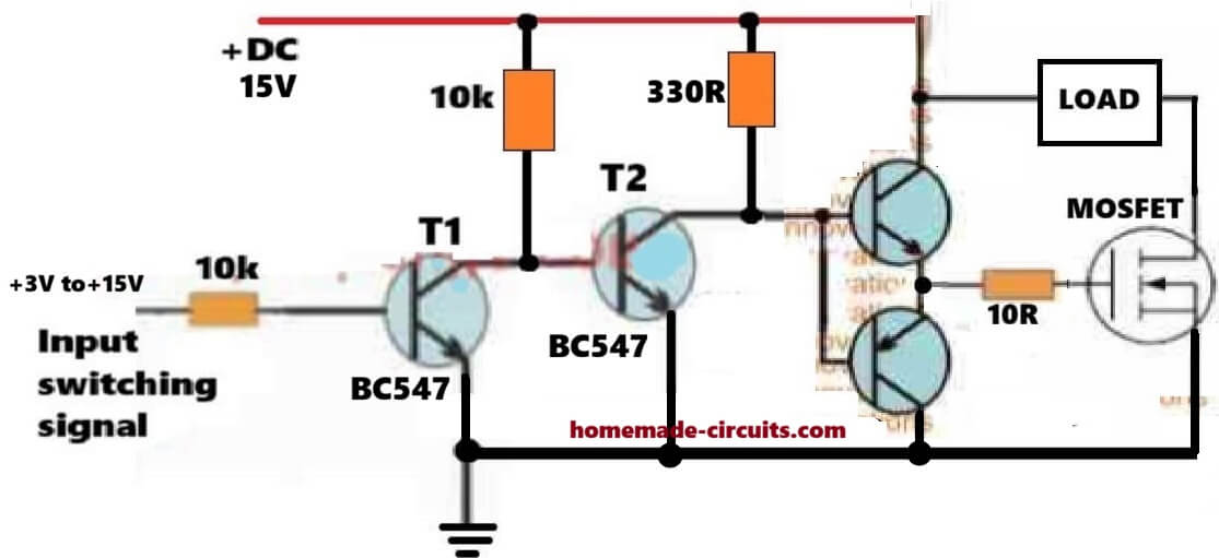
I can completely understand your situation, the modern logic MOSFETs may not be always easily accessible, so we have to depend on the standard 10V minimum VGs variants.
The 4.3V is due to the base/emitter drop caused across each of the BJTs in the totem pole configuration, since these are arranged as emitter followers.
For your case I would recommend combining the two designs and create a hybrid version as shown below. This would effectively solve the +10V hard gate drive requirement for the regular MOSFETs and yet could be driven from any MCU source with output as low as 3V, or higher.
Dear Swagatam, Whenever I’m in doubt or trying something new, I always come back and search your website. Thank you, I really enjoy your website, there is always something new to learn.
I have questions regarding these two MOSFET driver circuits. If I understand this correctly, the first circuit switches the MOSFET off with a positive signal, and the second circuit switches the MOSFET on with a positive signal.
On the second circuit, when the signal is low, the base of the PNP transistor is not connected to ground. Are no output from an Arduino (0V) the same as Ground (0V) to switch the PNP transistor On? And, would the 2nd circuit be suitable to switch a vehicle radiator fan on and off with a 5V Arduino signal, not pulsed?
Dear Jacques,
Thank you so much for your kind words. I am really happy to know that you enjoy visiting my website and learning from the articles. You have understood the basic operation correctly but both circuits actually turn the MOSFET ON with a positive input signal and OFF with a LOW input signal.
So now the difference is mainly in their gate driving arrangements.
Regarding your Arduino question yes, an Arduino output configured as LOW is effectively connected to its GND internally.
Therefore it can pull the PNP transistor base LOW through the 10k resistor and switch it ON. Just make sure the Arduino GND and driver circuit GND is connected together.
Regarding your radiator fan application, second circuit can be used for simple ON/OFF switching without PWM.
However with a 5V Arduino signal, its output gate voltage will be approximately 4.3V so you must select a MOSFET that can turn fully ON at this voltage. Also make sure the MOSFET can handle the fan’s high startup current and provide suitable protection against automotive voltage spikes.