In this post I have explained how to build an innovative inverter circuit with a single transformer that works both as an inverter and a battery charger transformer, I have explained the details from the following discussion.
The Circuit Objective
Though you may find many inverters having an integral battery charger, the section will mostly employ a separate transformer for implementing it.
In the following post I have explained a unique design which utilizes the inverter transformer for power inverting as well as for charging the battery.
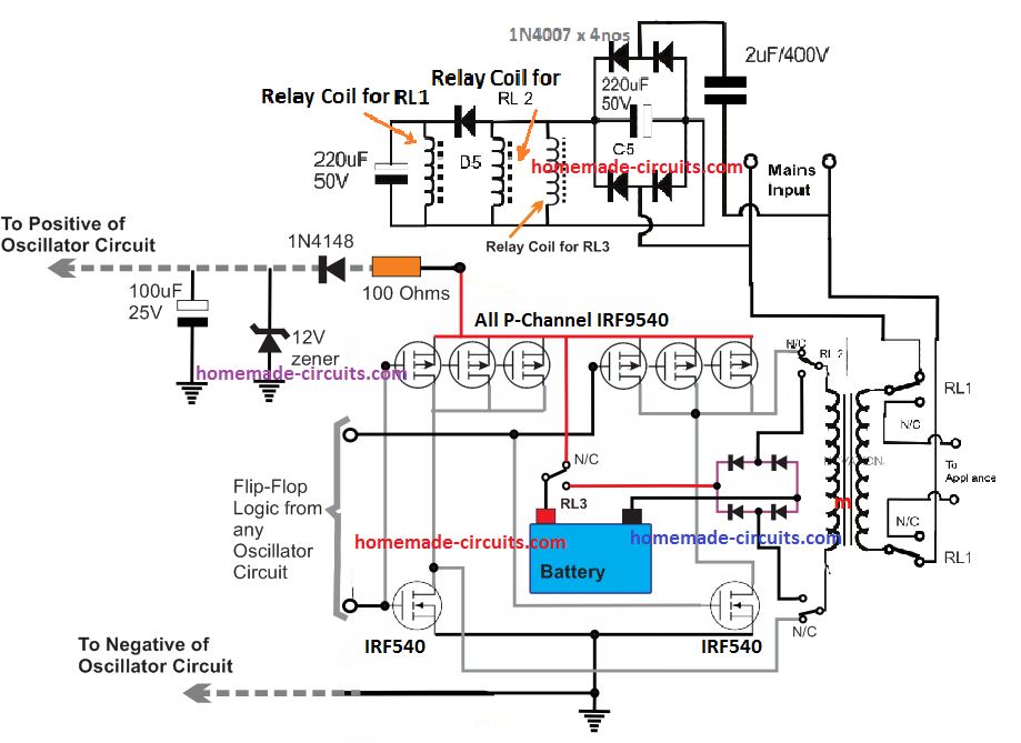
The circuit diagram below shows a design where a single power transformer is used for inverting purpose as well as for charging the battery when mains is present.
The good thing about the circuit is that the transformer doesn't employ separate winding for this, rather works with the same input winding and reverts DC to the battery with the help of a few DPDT relays.
The circuit can be understood with the following points:
How the Circuit Functions
The inverter section can be easiy recognized in the diagram, R1 to R6, including the T1 and T2 forms a general astable multivibrator circuit for producing the required 50 or 60 Hz pulses.
These pulses drive the mosfets alternately which in turn saturate the transformer by switching the battery voltage in it.
The secondary of the transformer generates the corresponding magnitude of AC which is finally used for operating the connected appliances.
The above configuration suggests an normal or ordinary inverter operation.
By adding a couple of DPDT relays in the above discussed operation, we can force the circuit to charge the battery in the prsence of an AC mains source.
The coils of the two relays are powered through a capacitive low current compact power supply, involving C6, C5, D1----D5.
The above circuit is connected to a mains AC source, this source is also connected to RL1 poles.
The second relay RL2 is wired up with input winding of the transformer.
In the absence of mains AC, the position of the relay contacts are in the N/C as shown in the figure.
In this position the mosfets get linked with the transformer input winding, and the battery with the circuit so that the inverter starts oscillating and the output appliances gets the AC power from the battery.
In the presence of mains AC the relay coils instantly get the required DC power and the contacts activate.
RL1 activates and connects the mains input to the transformer, the appliances also get connected with the mains AC in the process.
Also due to the action of RL2 the mosfets get disconnected from the transformer, while the the lower tap connects with D6.
Since the center is already connected to battery positive, the inclusion of D6 provides a half wave rectified voltage to the battery, which is effectively filtered by C3 so that the battery is able to get the required sufficient charging voltage.
The above charging process continues until mains is present, so it should be monitored manually. When mains fails, the action reverts into inverting mode without interrupting the appliance operations and by using a single transformer for both the operations.
C4 makes sure that RL1 always activates a shade later than RL2 for safety reasons.
CAUTION: THIS CIRCUIT IS DEFINITELY NOT RECOMMENDED FOR THE NEW HOBBYISTS, IT'S SUITABLE ONLY FOR THE EXPERTS. IF YOU ARE A NOVICE AND INTERESTED TO TRY THIS.... BUILD IT AT YOUR OWN RISK.
Parts List
- R1, R2 = 27K,
- R3, R4, R5, R6 = 470 Ohms,
- C1,C2 = 0.47uF/100V metallized
- T1, T2 = BC547,
- T3, T4 = any 30V, 10amp mosfet, N-channel.
- C3 = 47000uF/25V
- C4 = 220uF/25v
- C5 = 47uF/100v
- C6 = 105/400V
- R7 = 1M
- D1---D5 = 1N4007
- D6 = 1N5402
- RL1, RL2 = DPDT, 400 OHMS, 12V, 7 AMPS/220V
- Transformer = 12-0-12V, current as per requirement.
For only inverter design please refer to this ARTICLE
Using a 2-Wire Transformer
If you do not want to use a center tap transformer for the inverter, then you can use the following P-channel and N-channel MOSFET H-bridge inverter module for getting an identical single transformer inverter/charger results:


Comments
Can the two relays and bridge rectifier at the primary terminals of the transformer be removed so that the mosfet diodes be used for the charging?
I don’t think replacing the relays with MOSFETTs is possible in the above concepts…
Hello Sir. I need a circuit diagram on inverter with automatic changeover system
Hi Jedidiah, you can try implementing the following concept with any inverter for getting the intended results.
https://www.homemade-circuits.com/how-to-convert-inverter-to-ups/
Thank you
My inverter transformer using 2 IRF840 MOSFETs is just producing some sounds when an incandescent bulb is connected across the output. The bulb doesn’t light. Also, when there is no load at the output the transformer sparks at the output windings. how should I go about it please?
It looks like your transformer winding has internal short circuit, so please replace it with a new one and check again.
How do I charge a 120v DC battery bank with this circuit, what do I change?
If your inverter mosfets and transformer are rated to work with 120V, then the above basic setup will be the same, however the relay coils will also need to be rated at 120V
Sorry for asking much sir, but the final one now. Since a relay of about 200amps capacity would be big and probably expensive and might also not fit into the space provided, can a MOSFET of about 200ampsof current capacity be applied in place of the relay since it is going to be switching between the battery and the center-tap part of the transformer?. Thanks in anticipation
Sorry, no that might not be feasible, because an inverter/charger changeover circuit can be built only using relays and not using mosfets.
I really appreciate your kind response sir, thank you so much. But I’ve studied most high power inverters, however they’re without this high relay capacity you just recommended for me, their transformer primaries are screwed directly on the collector rails of the mosfets. Just with a single relay, I did not understand the magic they used in controlling the both the charging as well as inverting systems.
Ubochi, If you are using 2kva load at the output, then the transformer primary has to switch a 2kva current through the mosfets and the relay contacts, isn’t it? So isn’t the mosfet and the relay must be rated to handle that much current and load?? Moreover if your relay contacts are burning that clearly shows that the relay contacts are experiencing heavy load which is beyond their handling capacity.
Mr Swagatam, I have a difficult situation with your design here, please i really need your help.
I just designed a 2.5kva inverter using your recommended single centre-tap transformer method. I really appreciated the design on light loads, however, when I asked my client to turn on his fridge, the system shut down, then I found out that the 20am relays at the mosfet input to the transformer got burnt due to high current passage. Now, this is a very difficult situation for me now as removing the relays has cost me a lot of mosfets as the mosfets now have direct contact with the transformer primaries, especially whenever I try to input mains to charge the batteries. I don’t know what to do, please help me. Is there no other design that can work with a single relay?. Thanks
Hello Ubochi,
I am glad you could build the circuit successfully, however, you should have selected the relays appropriately according to the load.
For a 12V 2.5 kva load the relay contacts must be rated at 2500 / 12 = 208 amperes….that looks huge right, but that is how the relays must be rated, at 210 amps each for the mosfet side relays. If you replace the relays correctly with 210 amp relays then I think the inverter should start responding correctly. However for 210 amp relays the C6 capacitor will need to be increased to 5uF/400V
In a H-bridge design, transformers input volt are usually half of the battery volt. For example, a 12vDC to 220vAC inverter transformer is usually 6v-220v, while a 24vDC to 220vAC inverter transformer is usually 14v-220v. Now my question is this, with the above circuit, when AC mains is present, the transformer will return it’s winding voltage back to the battery I.e if it’s a 12v system, then 6v Wil be sent to the battery, or if it’s a 24v system, then 14v will be sent to the battery which will not be sufficient to charge the battery. So, how to solve this problem?
In an H-bridge circuit the mosfets will supply the full battery voltage to the load, if a 12V DC is connected to the H bridge mosfet drain, then this 12V will be alternately switched to the connected transformer primary.
If this is the case, then why use transformer with primary winding is half of the voltage of the battery in any H-bridge configuration? All inverters i have seen and repaired which are H-bridge configuration, uses transformer half the battery voltage. I opened a 48v -220v inverter yesterday, and the transformer is 26v primary and 220v secondary.
And if a mosfet of H-bridge gives full battery voltage i.e. 12v into 6v winding, then the output of the inverter should also double, like 440v thereabout.
Transformer winding will be half only when the H-bridge is a PWM based inverter, in which the load gets only the average 50% of the total Dc supply due to the PWM. If it is not a PWM then the load will get the full DC supply.
Thank you for the response. Now, in a PWM h-bridge, will this charging circuit be applicable?
The H bridge charger circuit shown above has nothing to do with H-bridge mosfets or PWM. In the presence of grid AC mains voltage, the transformer is directly connected with the battery through a bridge a rectifier and relays for the required charging of the battery.
I understand the circuit perfectly. My concern is the transformer. If AC mains is present at the 220v side of the transformer, then the other side of the transformer will have 6v because that is the default winding. Which is why I’m wondering if the 6v will work for charging a 12v battery.
Normally if the transformer is 12v-220v winding, then definitely there won’t be a problem. But since the transformer is not winded like that, what’s going to happen?
Yes, in that case a PWM based H-bridge cannot be used in this charger concept.
Thank you so much for the clarification sir. God bless you
You are most welcome!
Pls 24v ups my ups did not bring 230v output, it bring 170v why any help
Is your battery fully charged? And is the 170V with load or without load?
180v with load and battery is fully charge
Try reducing the load, and check the voltage. If the voltage rises with lower loads then the problem could be due to low power transformer and battery which are unable to handle the load that you are applying.
Helpful
does anyone has the PCB diagram to print a PCB form.
Thank you for your swift response.
I need your advice.
1) I want to use a 12-0-12v transformer with a 24v battery, what is your advice sir.
2) A 10amp 28VDC relay for this circuit been a battery charger inverter.
You are welcome Emmanuel!
1) It will work if your inverter frequency is PWM based and with 50% duty cycle
2) for 24v battery, the relay must be 24v also
Thanks sir.
In one of your article there is a diagram for 500w inverter. That is the diagram I am following. But in my case, my target watt is maximum of 150 to 200w. In other to achieve that, I didn’t use a transistor with the two MOSFET but I want to use every other components you have on the diagram.
So according to the diagram of 500w inverter.
1) Is it a PWM inverter or not.
I want to be clear on that sir.
2) And if it is not, how do I make it a PWM inverter with 50% duty circle as you have said sir.
Emmanuel, you can try the first or the second circuit from the following article, which are compatible with your transformer specifications.
The IC must be supplied 12V from a 7812 or any step down converter
https://www.homemade-circuits.com/modified-sine-wave-inverter-circuit-2/
Thank you for your apt response always.
Kindly help me with these analysis on the battery charger diagram if I am correct.
Relay 1 and 2 coils are connected before and after D5
The common pins are connected to the transformer
NO is connected to the appliance
NC is connected to mains input.
Please I want to know if I am correct with this analysis.
Thanks
That’s right, N/O of RL1 are also connected to the transformer 220V wires.
Thank you for your response. Please, how many pin does RL1 and RL2 has. Or probably not all the pins are used in RL2. Kindly help with this.
8 pin each, please Google DPDT relay you will easily get all the details.
EngineerSwagatam.
Good evening.
I am pleased to have found this page interesting and useful, as it teaches about power electronics. I am a hobbyist who recently dabbled in this investor issue. I have assembled this circuit in Proteus to be able to simulate it. But of course, the simulation is not given in the first instance since you have to understand the design. My big question: can this circuit work with the load and at the same time it can feed back the battery, in order to be able to work continuously 24 hours x 7 days? My thanks in advance for the attention given to this.
Atte.José Javier González.
Thank you Jose, I am glad you found this site useful!
Yes simulation might not sometimes give us the desired results, and we have to ultimately build and test a given project practically.
No, sorry, it is not possible to discharge a battery via an inverter and simultaneously charge the battery from its output, because the inverter will work with 10 to 20% losses which will never allow this process to succeed.
Swagatam Engineer.
Good evening. Thank you very much for your precious reply. I am studying all this topic regarding CA – CD Invertor based on your valued page www. His answer reveals the principle of energy: it is neither created nor destroyed. So based on this principle, do you mean I should design the circuit adding a second battery of equal voltage and amperage that feeds back the first battery? Or will the initial battery increase its capacity for the same inverter in question? My thanks in advance for the attention given to this.
Atte. José Javier González.
You are welcome Jose, no, even using two batteries will not help to produce power 24/7, eventually both the batteries will get exhausted.
Good day sir, an inverter I use well at home and charges well, when I give it to someone , it never charge a single volt with generator in that house because they don’t have power in the house. They use the generator to pump their 1.5hp pump. The inverter is serving during automatic changeover but not charging the battery at all. Please what could be wrong sir.
Thanks for always being there, Swagatam. How can I appropriately rate the breaker in auto changeover inverter charging system against sulfation tripping off.
Sorry Adeyemi, I do not have any idea about it.
Adeyemi, please check the DC voltage from the generator which is used for charging the battery, that will clarify the situation.
For auto cut off you can refer to the following concept:
Op amp Battery Charger Circuit with Auto Cut Off
you can use the transformer for pwm inverter with a 24 V battery
Evans, 16.5 V after rectification will give 16.5 x 1.41 = 23 V which is not sufficient to charge a 24 V battery. It must be at least 28 v
PWM is better since it allows waveform control.
Also sir swagatam,if u have an auto cutoff circuit for 24v, please help me with one. Sir in my last question,I was seeking to know if a transformer with an output of 16.5v can be used for an inverter with pwm. Thanks in advance.