A very simple automatic solar light system for illuminating your garden passages can be built using some LEDs, a rechargeable battery and a small solar panel. The system automatically switches ON the lamps at dusk and switches them OFF at dawn.
Main features
Although the following simple automatic solar LED garden light circuit looks simple, it includes a few interesting features which makes this design extremely adaptable, versatile, safe, efficient and long lasting.
The mains features are listed below:
- Automatic charging of battery during daytime with LEDs turned off, and automatic switching ON of the LEDs during nighttime.
- Proper current limiting for the battery to safeguard the battery from excessive charging.
- Current limiting for the LEDs which can be adjusted as per the required number of LEDs.
- Battery over-discharge protection ensures that the battery can never be overly discharged by the LEDs, which in turn ensures a longer life for the battery
How it Works
As can be seen in the following circuit diagram, the design basically consists of a solar panel, a couple of NPN transistors, LEDs, a battery, a few resistors and diodes.
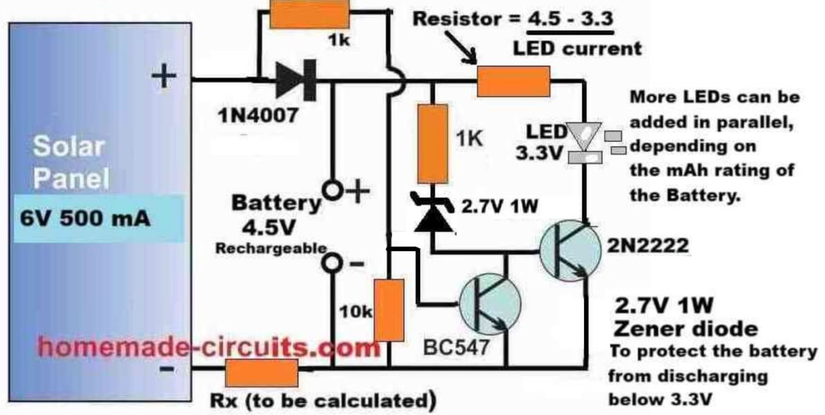
Referring to the circuit diagram above, the working of each of the components can be understood with the following points:
The solar panel supplies the peak voltage of 6 V, at 500 ma during daytime, which charges the battery as long as this voltage is available from the solar panel.
The resistor Rx keeps the charging current to a safe lower level so that even after the battery is fully charged, the minimal current does not harm the battery.
The value of the charging current determining resistor can be calculated using the following formula:
Rx = (Vsolar(peak) - Vbattery(full)) / Icharge
Rx = (Solar peak voltage - Battery full charge voltage) / Battery charging current
Example:
Solar Panel Voltage = 6V
Battery Full Charge Spec = 4.2V
Battery Charging Current (optimal) = 500 mA
Rx = (Vsolar(peak) - Vbattery(full)) / Icharge
= (6 - 4.2) / 0.5
= 3.6 Ω
Rx Power = (Vsolar(peak) - Vbattery(full)) * Icharge
= (6 - 4.2) * 0.5
= 0.9 watts or simply a 1 Watt
However, if you want better protection than just a current limiting resistor, you can opt for a regulated charging system, as discussed in the next design after this explanation.
The BC547 transistor ensures that the LED driver transistor using 2N2222 remains turned off, as long as a base voltage of at least 0.6 volts is available from the solar panel.
Meaning, until the voltage from the solar panel has not dropped below 0.6 V, the BC547 transistor remains switched ON, causing the base of the 2N2222 to remain grounded, and turned off.
Therefore, until it is significantly dark or until the solar panel is able to supply at least 0.6 V to the BC547 base, the 2N2222 remains switched off, which in turn causes the LEDs to remain shut off.
Once the solar panel voltage drops below 0.6 V, the BC547 transistor slowly starts turning off, causing the 2N2222 to slowly start turning ON.
As the 2N2222 slowly turns ON, its collector LEDs also begin slowly getting illuminated, using the stored power from the battery which was charged during the daytime using solar energy.
Once it is completely dark and the BC547 is fully turned off, the 2N2222 BJT conducts fully causing a full illumination on the LEDs.
The LEDs now illuminate fully using the stored energy from the battery, and the battery slowly starts depleting its power through the LEDs.
The battery keeps the LEDs illuminated until the battery voltage has drained down to its lowest discharge level, which happens to be around 3 V for the 4.5 V battery shown in the diagram.
However, as we know that a BJT can conduct only until its base voltage is around 0.6 V higher than its emitter voltage.
But since the base of the 2N2222 is clamped with a 2.7 V zener diode, it means that the base voltage of the 2N2222 needs a minimum of 2.7 + 0.6 = 3.3 V to enable its proper conduction.
So, when the battery voltage drops to around 3 V, the base of the 2N2222 does not satisfy the minimum required base voltage of 3.3 V and thus it turns OFF.
In this situation the LEDs also shut off, preventing any further discharge of the battery, which protects the battery from over discharging.
A series resistor with the LED positive line ensures that the LEDs are protected from over current and are always safely illuminated without any possible harm or damage.
The limiting resistor can be calculated using the following formula:
R = (VBattery - VLED) / ILED
R = (Battery Voltage - LED forward voltage) / Total LED safe Current.
Example:
Battery Voltage = 4.2V
LED Voltage = 3.3 V
LED Current = 20 mA
Then,
R = (VBattery - VLED) / ILED
= (4.2 - 3.3) / 0.02
= 45 Ω
R (Power) = (4.2 - 3.3) * 0.02 = 0.018 watts or simply a 1/4 watt should work...
The next morning when sunlight falls on the solar panel, the BC547 yet again disables any conduction of the 2N2222 BJT and the LEDs, initiating a fresh charging cycle for the battery.
The above cycle now keeps repeating each day and night providing the required automatic illumination of the garden premise using this simple, versatile garden LED light circuit.
You may also like this PIR Controlled Solar Garden Light Circuit
Solar Garden Light with Regulated Battery Charging
The following diagram shows how the above simple design can be upgraded into an automatic solar garden light circuit with regulated battery charging.
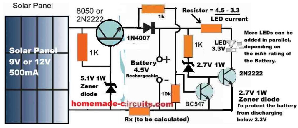
The automatic operation of the LED lamp stage is actually exactly identical to our previous design, the only difference being the inclusion of the voltage regulator stage incorporating another 2N2222 BJT in an emitter follower configuration.
As we know that in an BJT emitter follower configuration, the emitter voltage of the BJT follows the base voltage, meaning the emitter terminal of the BJT replicates its base voltage.
However, due to the BJT's internal base/emitter voltage drop of 0.6 V, the emitter voltage is always around 0.6 Volts lower than the base voltage.
In the above regulated solar garden light circuit diagram, since the base of the left side 2N2222 emitter follower regulator BJT is clamped with a 5.1 V zener diode, means that its base voltage is fixed at 5.1 V, regardless of the solar panel voltage.
Therefore, the emitter voltage of this regulator 2N2222 BJT will be always fixed at around 5.1 - 0.6 = 4.5 V.
This 4.5 V fixed output is what we require for a safe charging of our 4.5 V battery, which means the 4.5V battery can be never charged above its full charge level of 4.5V, ensuring a safe regulated charging for the battery.
Parts List
- Resistor, 1k, 1/4 W CFR = 3
- Resistor, 10k 1/4 W CFR = 1
- LED limiting resistor and Battery limiting resistors as discussed previously.
- BJT 2N2222 = 2
- BJT BC547 = 1
- Rectifier Diode 1N4007 = 1
- Zener Diode 5.1 V 1/2 watt = 1
- Zener diode 2.7 V 1/2 watt = 1
- LEDs as per requirement and battery capacity.
- Solar Panel = 9V to 12V, 500 mA
Using NPN Transistors
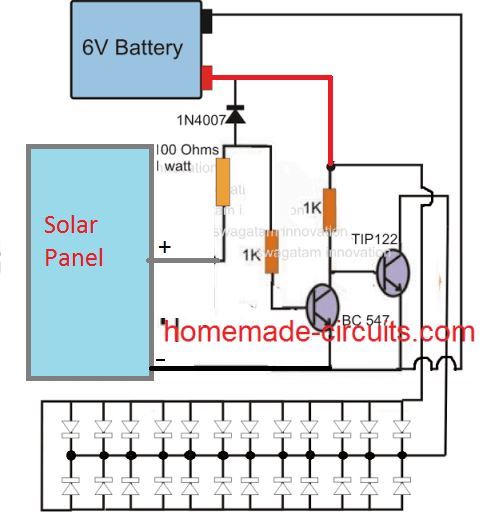
The above explained designs can be also replicated using two NPN transistors as shown in the following diagram:
Solar Pathway Light Circuit with Constant Voltage
If a Li-Ion battery is intended to be used for the above explained circuit, a constant voltage feature becomes crucial for safeguarding battery life and prolonging it.
The following circuit show how this may be done by adding a simple voltage follower regulator circuit:
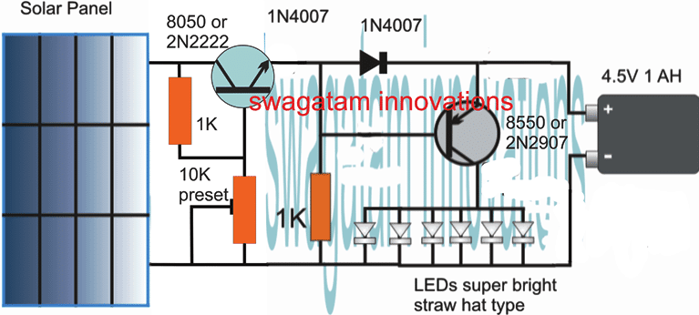
If a 3.7V Li-Ion battery is used, make sure to adjust the 10K preset to achieve precisely 4V across the output points where the battery is supposed to be connected, do this adjustment without connecting the battery.
The 4V level ensures that the battery is never overcharged (at 4.2V) and this also allows the circuit charge the battery without a constant current supply.
1.5V Solar Garden Light with Enhanced Features
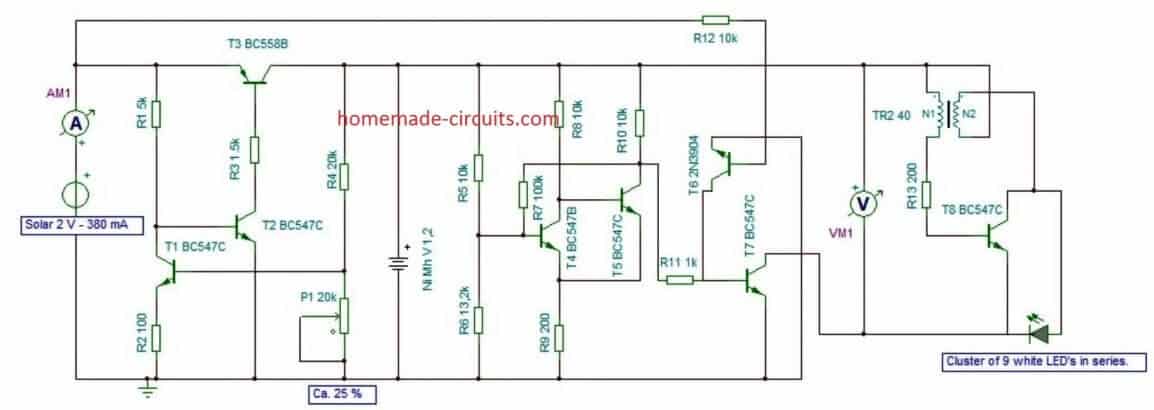
The following solar powered garden light was designed by Mr. Guido which includes additional features such over charge and low charge cut off for the battery and with a Schmidt trigger.
This ensures that the connected battery is never allowed to charge or discharge beyond unsafe levels.
The main attraction of the circuit is the use of a single rechargeable AAA penlight cell, which is able to light up a 3.3V high bright LED through an attached Joule thief circuit.
High Power 12V Garden Light Circuit
The following image shows a high power automatic garden porch light circuit using a 12V 7 Ah battery. The LEDs used are high power 1 watt LED each. Since 9 LEDs are used the total power output becomes 9 watt.
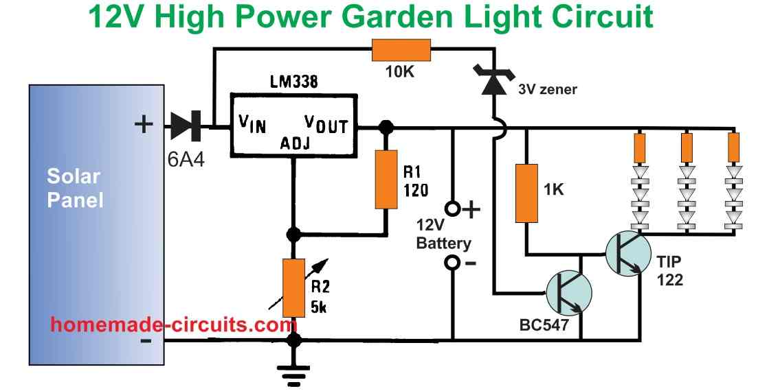
The circuit is designed to automatically switch ON the LEDs when the darkness level drops sufficiently and the solar panel voltage drops below 3 V.
The LED series resistor values can be calculated using the following formula:
R = Battery Supply - LED FWD V Drop / LED Current
= 13 - (3.3 x 3) / 0.3
= 2.1 / 0.3 = 7 Ohms
Resistor wattage = 2.1 x 0.3 = 0.63 watts or 1 watt.
The solar panel can be rated at 18V, 3 amp. The battery specification is 12V, 7 Ah. The solar panel output voltage is regulated using the LM338 voltage regulator.
Make sure that the 5K pot of the LM338 circuit is precisely adjusted to produce 14V for charging the 12V battery.


Questions & Answers
you can modify the above circuit simply by calculating the resistor as per the given formula.
may be you did not notice the message written in BOLD letters just under the diagram
Go and check the cached impression in Google you would know it was done a long time ago.
Check the previous comments dated May14, June7, it's always wise to check the facts before criticizing.
I regret it if I misunderstood you, I thought you were saying that the written corrections were made immediately after listening to your suggestion.
Correcting the image is time consuming and involves more effort therefore I put in the text form.
Anyway, cheers!
The initial diagram had a zener diode at the base of the transistor which I removed later on for making the circuit more responsive and efficient.
you are most welcome!
hello SM,
is there any chance you can work on a circuit similiar to the following ebay link? http://www.ebay.com/itm/LED-Solar-Power-Motion-Sensor-PIR-Wall-Mount-Garden-Path-Yard-Door-Light-Lamp-/310657821723
its PIR solar light running off 3x 1.2v rechargeable batteries? Ive looks around google for a similiar circuit but no luck, so i decided to try my luck with you! plmk.
Thanks
G.
Hello G,
The above circuit and the second last design presented in the following link can be easily combined to produce identical results:
https://www.homemade-circuits.com/2012/09/pir-controlled-led-driver-circuit.html
Some tweaking would be required to make the design perfect, though.
Hello friend,
With the transistor as a switch there won't be well defined switching rather the transition would be in a gradual manner.
As long as the solar voltage is above 4.5V, the LEDs would be completely shut off, as the panel voltage begins dropping downward, the LEds would begin illuminating dimly and start getting bigger as the voltage drops further, finally when the solar voltage becomes almost zero, the LEDs would glow at their maximum rated intensity.
It would hardly dissipate anything, you may try increasing it to 2k2.
Just built this and tested it out and it works great.
I'm curious though if maybe the 1k resistor can be lowered and what kind of value would be safe to make the LEDs brighter.
I would like them extremely bright, but don't want to blow them obviously.
At the moment they light up, and they are fairly bright, but not as bright as I've seen these LEDs get before (I'm using 8mm standard 20ma LEDs that you can get from Radioshack)
Thank you Lucky Day,
reducing iK resistor wouldn't be a good idea, rather you can try inserting a resistor in series with each LED and remove the common 10 ohm resistor.
the value for the individual resistors could be around 2 ohm, 1/4 watt
If you are using the configuration that's shown in the above article then you may have to first step down the solar panel voltage to 6V to safeguard the battery.
You can use a 7806 IC at the input of the circuit such that the panel voltage passes through the IC and then reaches the above circuit.
You can take the help of the following post for knowing the 7806 connection details, it will exactly same as shown in the following circuit:
https://www.homemade-circuits.com/2012/03/how-to-make-simple-dc-to-dc-cell-phone.html
Please refer to the previous comment posted just above this comment..
hi, i used 4.5 v solar panel, and i used 3,7 A li-ion battery. Do i have to change anything to the circuit? thanks.
Hi, 4.5V will not do, you will need at least a 6v panel for the above circuit.
Hi swagatam bhai ty for help
Maine soler automatic circuit banai ager mujhe 10 watt soler 12v 7ah or 4.5v led h uske liye mujhe kya krna chahiyye help me
Hi Shiraz bhai you can use the circuit that's shown in the above article.
just replace the shown transistor with TIP127, connect the LED across collector/ground and battery at the given position
please mention the LEd wattage and voltage also so that I can calculate and provide you the series resistor value for the LED
Thanx you so much mere bhai
my pleasure bhai.
What should be the specification of solar panel if we want to charge a 12V battery (5Ah or 2.5 Ah) for using 4-5 power LEDs ? What changes are to be made in the above circuit so that LEDs can glow for atleast 8-9 hours?
Thanks.
Thanks for the reply sir.,actually LEDs will not be used simultaneously,I want that the battery gets charged during day time and used at night. Whether a 12V(5AH) battery is sufficient or not? Also,what should be the 'Wattage' rating of the solar panel?These power LEDs are connected in series and as far as I know the 1 watt i.e. power LED requires 350 ma current.What is the value of resistance that is needed to be connected for this 5 Watt LED circuit?
Thanks..
An 18V, 1 amp solar panel would be OK, if only battery is charged, if LEds are also simultaneously used then you would require a 3 amp solar panel.
the backup time will entirely depend on the battery AH and the led current, led current should be approx 1/10th of battery AH for 9hrs operation.
Here are the calculations:
1watt LED x 12 hours = 12 watt hours will be the led consumption
12watt hours / 12V batt = 1ah battery will be sufficient, so 5ah is more than enough.
12/5 hours sunlight = 2.5 watt solar panel will do
2.5/battery V = 2.5/12 = 0.208amp solar panel will be required
the above calculations was done as per the following article:
https://www.homemade-circuits.com/2013/05/how-to-calculate-and-match-solar-panel.html
refer to the formula given at the bottom of the following article for calculating the resistance value:
https://www.homemade-circuits.com/2013/06/universal-high-watt-led-current-limiter.html
Ye jo aap ne 4.5 1h ki battery use ki diagram me ager ye bttery ki jagha 12v26ah ki battery lagau to transistor kitne no ka use karu ?
use TIP127
Sir, is it ok if I use 6V battery?
yes it's OK
Sir
I want one circuit diagram.and I want automatically ON & OFF the street lights by using L.D.R's and lanp which is connected to solar energy
Basavraj, you can try the following design:
https://www.homemade-circuits.com/2012/10/automatic-40-watt-led-solar-street.html
Sir, This is exactly what I need except that I need to use a 15 watt 17 volt solar panel with an output of .89 amp. What components do I need to replace in order to run this solar panel? I'll be charging 2 or 3 18650 batteries in parallel with a 2500mah capacity each. thank you in advance.
Lorenzo, you'll need to change the transistor with a BD140, and reduce the 1K resistor value to may be 220 ohms 1 watt
also you'll need to connect the 3.7V batts in series for making its voltage compatible with the panel output…. for more safety you can think of using a LM338 variable regulator IC at the input…..
Hi, Can you provide a solar lamp with LDR circuit details ?, Something similar to A LTTER OF LIGHT Program.
LDR won't be required, the solar panel will itself work like a light sensor…… the concept explained in the above article is a good example
But on cloudy day without sun light, LED will start glowing as current is zero from panel. But we may not need LED light as it is day. Will LDR help here?
Yes, it will start glowing at a proportionately dim level depending on how much overcast it may be…LDR will not help…. you will need a relay changeover instead of a battery changeover, as shown in the following circuit:
https://www.homemade-circuits.com/2015/03/solar-led-lights-with-charger.html
Hello, I liked your schematic because it appeared to be very straight forward, however when i went to make it for myself the LED lit up but would not turn off when light was exposed to the solar panel. when looking for transistors i could not find the exact transistor you call for but i did get a 2n2923 transistor i thought would work. since this is the only active component I'm not sure if the problem could be there or somewhere else. since we are using a battery pack for 8 double A's that should cause it to act as a 12v battery we are using a 750 resistor along with the 1K resistor. currently there is only one LED connected and I believe everything else follows the schematic exactly. Any ideas or suggestion what could be causing this problem would be greatly appreciated.
Hello, 2N2923 is an NPN transistor, so it will simply not work, it has to be a PNP, or may be you can use two 2N2923 for getting the same results.
I should also be able to include a picture if you think that would be helpful
Ahh thank you I though it was a pnp transistor. But since it's not is there a way to know just by the label number if it is?
The label will not inform regarding its polarity, you may have to refer to its datasheet online to learn the details….
.
Hello Swagatam
Your site is of great help.
I have a query in above circuit.
What is purpose of 10Ohm,1/4W resistor? How does it act as current limiting resistor?
My understanding was resistor was added for voltage drop in battery voltage of 4.5V to LED spec voltage.
Can you provide the voltage/current/power of LED used?
thanks unknown,
the 10 ohm resistor is for providing some sort of current limiting to the attached battery while the solar voltage is available, and it also acts like a current limiter for the LEDs while the solar panel voltage is absent and the LEds switched ON.
the LEDs can be 5mm/ 20mA type white LeDs
Hello Swagatam,
Thanks for reply.
I am planning to use single 1 Watt LED (3.2 V, 350mA), so what should be resistance value and wattage of resistor?
Can i use 3.6V, 1000maH battery?
Hello Nishanth,
3.6V/1000mAh will get drained very soon with a 1 watt LED, it should be at least a 2AH battery.
you can use a 2.5 ohm, 1/2 watt resistor
Hello Swagatam
Can you explain me on how you came up with 2.5 ohm, 1/2 watt resistor?