In this article I have explained a simple line follower robot circuit, also known as line tracker vehicle, using just a couple of op amps from the IC LM324 and a few other components, without using complex Arduino or microcontrollers. It means this project can be built without any coding, just by using discrete components, and by any new hobbyists, with most effective results.
What is a Line Follower Robot Vehicle
A line follower robot vehicle is a form of Automatic Guided Vehicle (AGV) which runs by detecting a white line drawn or embedded on ground.
The signal from the detectors command the motorized wheels to automatically turn and adjust in accordance with the line, giving an impression that the vehicle is following the line. Hence the name line follower.
Basically the detectors are in the form of photo resistors such as LDRs or semiconductors light detectors such as photo diodes or photo transistors.
A couple of such light detectors are used which detect the reflected light from the white line and switch a transistorized circuit or op amp based comparators, which in turn control the wheel motors of the robot vehicle to maneuver in accordance with the turns and curves of the white line on the ground.
Using Window Comparators
In the proposed line follower robot vehicle circuit, we have used a couple of op amp comparators was engaging the motors into the balancing act.
The op amps are rigged as window compartaors. As the name suggests, a window comparator compares the input signal from the detectors with two extreme voltage references which constitute the "window" thresholds.
As long as the input signal level is within this "window" reference thresholds, the output of both the op amps maintain high logic across their outputs.
However, in an event the input signal tends to cross the reference thresholds, the relevant op amp output turns low, resulting in opposing outputs from the op amps.
This unbalance prompts the output devices to correct the situation by switching of the loads appropriately.
How the Circuit Works
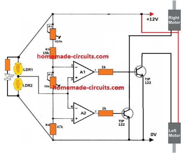
Referring to the circuit diagram of the line follower robot vehicle below, we can see two op amps from the IC LM324 configured as window compartaors.
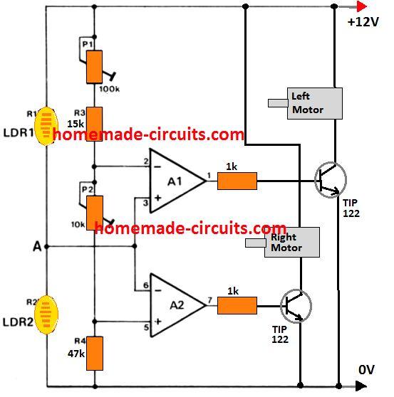
The upper op amp is wired to control the upper threshold limit, while the lower op amp is connected to control the lower threshold limit.
The inverting input of op amp A1 and non-inverting input of op amp A2 are clamped with fixed reference voltage
The non-inverting input of op amp A1, and the the inverting input of the op amp A2 are tied together and used for sensing the variations in the input signal from the light detectors.
The two Light Dependent Resistors, LDR1 and LDR2 which act like light sensitive devices are positioned as light detectors, such that they receive the reflected light from the white line uniformly on them.
As long as the light on the LDRs are adequately high and uniform, the pin3 of A1 remains higher than its pin2, since LDR1 is attached with the positive line. This causes its output to go high.
Likewise, pin6 of A2 is held lower than its pin5 due to the LDR2 connection with the ground line, and this enables the output of A2 to stay high.
In other words, when the LDRs are uniformly lit, the non-inverting (+) inputs of the both the op amps are held higher than their inverting (-) inputs causing their outputs to go high.
With both the outputs high, the transistor drivers keep the respective motors running uniformly, which correspondingly allows the vehicle to run smoothly over a straight line.
How the Robot Vehicle Follows the Line
When a curving white line is encountered, one of the LDRs deviates from the line causing a difference in light at point A of the circuit. This subsequently causes the relevant op amp output to go low and a momentary stoppage of the relevant motor.
In this situation, the other side motor which is still operational forces the robot vehicle to turn towards the bending angle of the line, which brings the shaded LDR back in the illuminated region of the white line. When this happens both the motors again become operational enabling the robot vehicle to run normally.
The above automatic ON/OFF switching across the left/right motors in response to light variations from the bending white lines forces the robot vehicle to keep adjusting and maneuvering in accordance with the white line.
How to Build the Robot Vehicle
In one of my earlier posts I have explained how a simple remote controlled vehicle could be built using just a couple of motors attached to the rear edge of a rectangular board, and pair of dummy wheels at the front edge of the board.
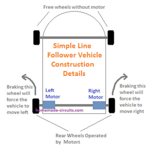
For the proposed line follower robot circuit also, we employ a similar construction for the vehicle, as exhibited in the above figure.
The arrangement looks pretty simple, the rear wheels are attached with motors which are controlled by the transistor drivers across the op amp outputs.
When the robot vehicle deviates from the line, the difference in the light level on the LDRs switches OFF one of the op amps, halting the relevant motor.
This forces the opposite side motor which is operational, to turn towards the side of the halted motor, meaning if the left side motor is braked, the robot vehicle will be forced to turn toward left, adjusting to the bending line, on the same direction.
This also suggests that the left/right motor integration with the op amp outputs should be appropriately done such that bending direction of the line and the motor which is being stopped are on the same side of the vehicle.
How to Position the LDRs
Since the two LDRs (LDR1 and LDR2) are supposed to sense the reflected light from the white line uniformly, their orientation should be perpendicular to the length of the line, as shown below.
Here, we have assumed the robot vehicle to be running from right to left, following a laid down line in the same path.
The LDRs total width should fall within the width of the line.
The LDRs and the LED should be installed at the bottom surface of the vehicle, and preferably at the rear side, just under the rear wheel set.
The indicated LED is a white LED with a series 1K resistor. It must be positioned close to the LDRs and at the center, ensuring that the light from the LDR don't reach the LDRs directly, instead the light should reach the LDRs by reflection from the white line under them.
Motor Specs
The motors can be any permanent magnet brushed type, but it should be equipped with a gear box to ensure the movement of the vehicle is appropriately slow and steady.
The power rating of the motor should be as per the load which the robot vehicle is supposed to carry. This can be tested through some practical experimentation.
How to Set Up
To set up this line follower robot vehicle circuit, you will have to arrange a small strip of white line painted on a flat surface, or a white tape stuck on the flat surface.
Position the system (without wheels) over the line, as indicated in the previous diagram, such that the LDRs and the LED are correctly adjusted inside the width of the line.
Switch ON power, the white LED should illuminate the area under it brightly. Adjust the two presets until the both the motors are switched ON simultaneously.
Now shift the unit slightly on the right so that the LDR1 moves out of the white line.
The left motor should stop. If it doesn't then adjust the P1 until the left motor just stops.
Next, move the unit slightly on the left so that the LDR2 moves out of the white line. This should halt the right side motor. If it doesn't then adjust the 10k preset until the right side motor just stops.
This will complete the set up procedures and now you can install the wheels on the motors and use this guided vehicle to automatically follow a laid down track on the ground.
White Line vs Black Line
The proposed line follower system is based on a white line embedded on the ground, instead of a black line. The advantage of using a white line instead of a black line are as follows:
White line looks more elegant and decent compared to black line.
White line based line follower can work even in total darkness or dim ambient lights.Black light based designs normally require an external illumination to keep the vehicle operational.
A white line based AGV works more accurately regardless of the tile color, except for tiles which are extremely white or equivalent to the color of the white line.
Converting the Vehicle into a Black Line Follower
Despite of the above advantages, if the user prefers the robot vehicle to follow a black line, then the system could be easily transformed to do so through the a few quick modifications in the proposed design.
The user just to interchange or swap the input pin connections of the op amps with the presets, and remove the LED associated with the LDRs.
Another Simple Line Follower Circuit
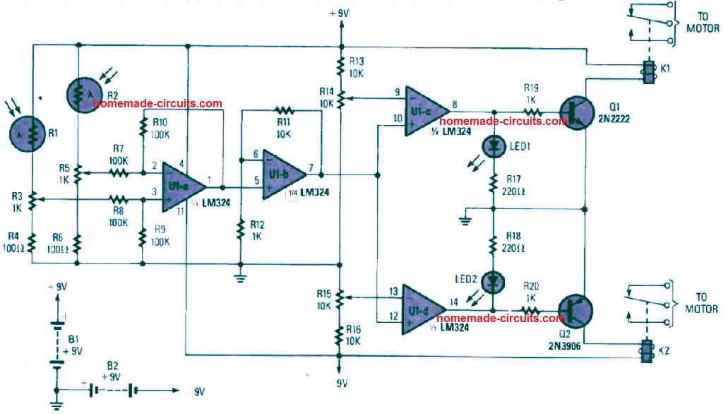
The op amp U1a flip flops its output from positive to negative and vice versa, in response to changing light levels across the two LDRs.
This response is amplified by the U1b op amp and fed to the driver op amps U1c, U1d.
When light reflected from the line falling on LDR1 (R1) is high, U1c's, U1d's non-inverting inputs get a positive signal, which causes their outputs to turn positive.
This positive from their outputs causes Q1 to switch ON since it is an NPN, and this turns ON the connected relay, which in turn causes the relevant motor on relay K1 to turn off, so that the vehicle can twist itself momentarily and correct its orientation until a uniform light is received on the LDRs.
On the other hand, if the opposite happens that is if LDR2 (R2) gets more light from the ground due to a disorientation of the vehicle, or maybe due to the line itself making a curve, this results in a negative voltage to be delivered on the non-inverting inputs of the U1c, and U1d, whose outputs now turn negative.
The negative logic is now responded by the PNP transistor but NPN transistor stays unbiased and does not conduct.
The PNP relay conducts and stops the relevant connected motor in order to ensure that the vehicle twists itself and corrects the orientation until both the LDRs have equal light on them.
Another White Line Follower Circuit (Steering Control)
The sensors applied to check the white line is built using a couple of light dependent resistors (LORs) that are targeted at both sides of the line to ensure that each LDR looks at half white half dark sections of the ground. The white line is lit up by means of a bulb to make sure that the LDRs include a comparatively low resistance.
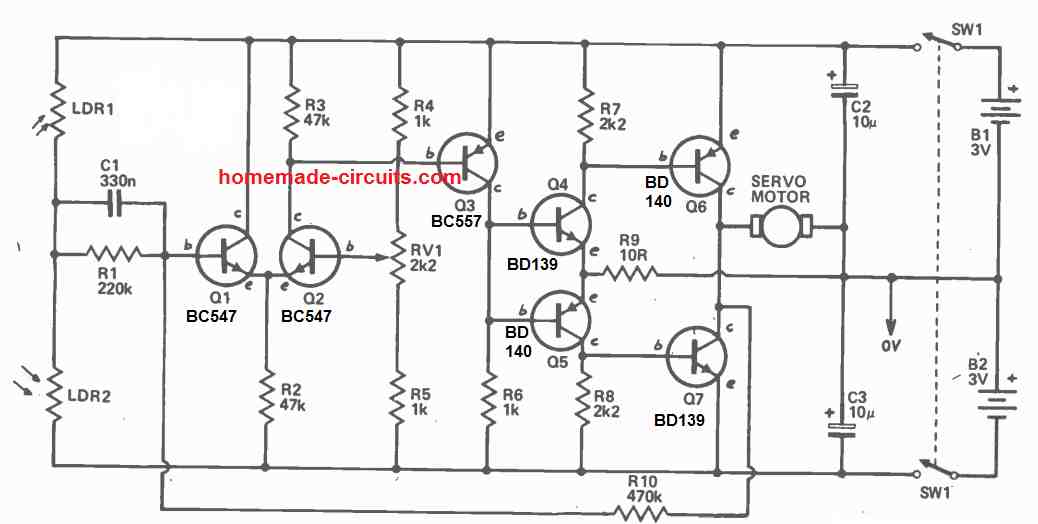
If the car or the vehicle is shifted off the center line one of the LDRs will witness higher percentage of 'white' causing its resistance to drop proportionately. Since both the LDRs are hooked up in series connection across the supply voltage, it implies that the voltage at the junction of the LDRs will change as the vehicle travels while following the twisting white line.
This varying voltage is compared with the setting of the preset RVI through transistors Q1 and Q2. The error signal thus generated adjusts the servo motor rotational direction accordingly which attempts to compensate the error, ensuring the robot vehicle adjusts itself and follows the white track correctly.
The resistor R10 provides the negative feedback in order to minimize the 'open loop gain', whike the dynamic feedback is supplied by means of the capacitor C1, which is positioned to cut down overshoot.
Remember that the servo motor shown in the above figure is supposed to be configured with a steering mechanism of the vehicle, so that the steering is appropriately adjusted by the motor for keeping the vehicle correctly focused on the white line.
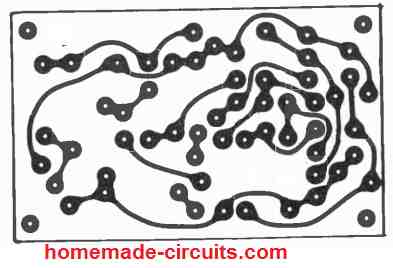
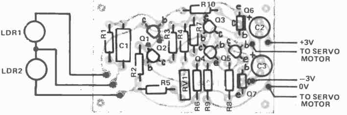
PCB Designs


Comments
Hello sir, I have long intended to install a floor cleaning robot that follows a predetermined trajectory. Now I read the article about using Ic lm324 to assemble a circuit to show the robot’s path, so I would like to ask if you can draw a white line to show the robot a bold path. Do those grains and lines affect the aesthetics of the house?
Hello Thieu,
Yes, those white lines can affect the aesthetics of the house, although it depends on the thinking of the house owner and his priorities.
Sir,
In the ending paragraph and in the schematic it mentioned as servo motor. I am confused.
Thanks,
K. Kausik
Yes, in the last diagram a servo motor is used, I was previously referring to the first op amp design.
However the last diagram is not designed by me so solving any related queries may be difficult for me.
Happy MAKEAR SANKRANTI ,SIR.
1) In the above mentioned circuit, where 4 op amps has been used, can turn in either direction, right ? ?
2) A servo motor has 3 lead. Positive, negative and signal. In the steering controlley circuit do I need any adjustment in the servo motor? ?
3) Is there any way to couple both the circuit by using only 2LDR. ( The circuit that using two relay may be helpful but how could I able to save those relays ? Any adjustment? ?)
Thanking you,
K. Kausik
Happy Makar Sankranti Krishnendu,
The circuit explained in the above article does not work with servo motor, it works with PM motors or permanent magnet motors with gear box. So a servo motor cannot be used with the above circuits.
THANK YOU,
Mr. Swagatam, Sir.
Simple ELECTRONICS is SIMPLY SUPERB.
Let me to give a try……
My pleasure Krishnendu, Glad you liked it!