In this post I have explained a two op amp IC 741 and LM358 based auto cut off battery charger circuits which are not only accurate with its features but also allows a hassle free and quick setting up of its high/low cut-off threshold limits. High current batteries can e also charged using these circuits.
The idea was requested by Mr. Mamdouh.
Circuit Objectives and Requirements
- As soon as I connect the external power automatically it will disconnect the battery and supply the system, in the meanwhile charging the battery.
- Overcharging protection ( which included in the above design).
- Battery low and full charging indications (which included in the above design).
- Also i don't know what is the formula to help how to determine the voltage required across my battery to charge it with( battery will be extracted of old laptops.total will be 22V with 6 apms at no load)
- Furthermore, I don't know the formula to indicate how long my battery will last, and how to calculate the time if i want a battery to last me two hours.
- Also, the cpu fan will supplied by the system too. It would be great too to add the option of a dimmer, my original plan was to vary between 26-30 v not need much more than that.
Circuit Diagram
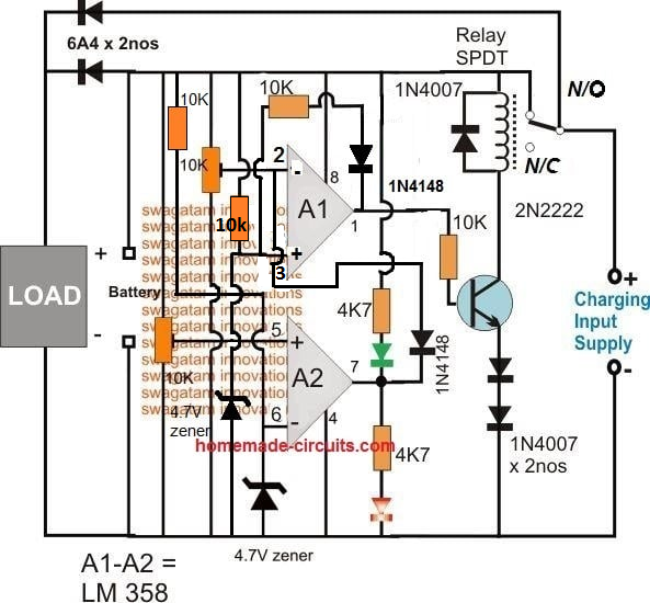
The Design
In all of my previous auto cut off battery charger controller circuits I have used a single opamp for executing the full charge auto cut-off, and have employed a hysteresis resistor for enabling the low level charging switch ON for the connected battery.
However calculating this hysteresis resistor correctly for achieving the precise low level restoration becomes slightly difficult and requires some trial and error effort which can be time consuming.
In the above proposed high current auto cut off low high battery charger controller circuit two opamp comparator are incorporated instead of one which simplifies the set up procedures and relieves the user from the long procedures.
Referring to the figure we can see two opamps configured as comparators for sensing the battery voltage and for the required cut-off operations.
Assuming the battery is s 12V battery, the lower A2 opamp's 10K preset is set such that its output pin#7 becomes high logic when the battery voltage just crosses the 11V mark (lower discharge threshold), while the upper A1 opamp's preset is adjusted such that its output goes high when the battery voltage touches the higher cut off threshold, say at 14.3V.
Therefore at 11V, the A1 output gets positive but due to the presence of the 1N4148 diode this positive stays ineffective and blocked from moving further to the base of the transistor.
The battery continues to charge, until it reaches 14.3V when the upper opamp activates the relay, and stops the charging supply to the battery.
The situation is instantly latched due to the inclusion of the feedback resistors across pin#1 and pin#3 of A1. The relay becomes locked in this position with the supply completely cut off for the battery.
The battery now begins slowly discharging via the connected load until it reaches its lower discharge threshold level at 11V when the A2 output is forced to go negative or zero.
Now the diode at its output becomes forward biased and quickly breaks the latch by grounding the latching feedback signal between the indicated pins of A1.
With this action the relay is instantly deactivated and restored to its initial N/C position and the charging current yet again begins flowing towards the battery.
This auto cut off low high battery charger circuit can be used as a DC UPS circuit also for ensuring a continuous supply for the load regardless of the mains presence or absence and for getting an uninterrupted supply through out its usage.
The input charging supply could be acquired from a regulated power supply such as an LM338 constant current variable constant voltage circuit externally.
How to Set the Presets
- Initially keep the 1k/1N4148 feedback disconnected from the A1 op amp.
- Move the A1 preset slider to ground level, and move the A2 preset slider to the positive level.
- Through a variable power supply, apply 14.2 V which is the full charge level for a 12 V battery across the "Battery" points.
- You will find the relay activating.
- Now slowly move the A1 preset towards the positive side until the relay just deactivates.
- This sets the full charge cut off.
- Now, connect the 1k/1N4148 back so that the A1 latches the relay in that position.
- Now slowly adjust the variable supply towards the lower discharge limit of the battery, you will find the relay continues to remain switched OFF due to the above mentioned feedback response.
- Adjust the power supply down to the lower battery discharge threshold level.
- After this, begin moving the A2 preset towards the ground side, until this turns A2 output to zero which breaks the A1 latch, and switches ON the relay back to the charging mode.
- That's all, the circuit is fully set now, seal the presets in this position.
Answers for other additional questions in the request are as given under:
Formula for calculating full charge cut off limit is:
Battery voltage rating + 20%, for example 20% of 12V is 2.4, so 12 + 2.4 = 14.4V is the full charge cut off voltage for a 12V battery
To know the battery back up time the following formula can be used, which gives you the approximate battery back up time.
Backup = 0.7 (Ah / Load Current)
Another alternative design for making an automatic over/under charge cut-off battery charger circuit using two op amps, can be seen below:
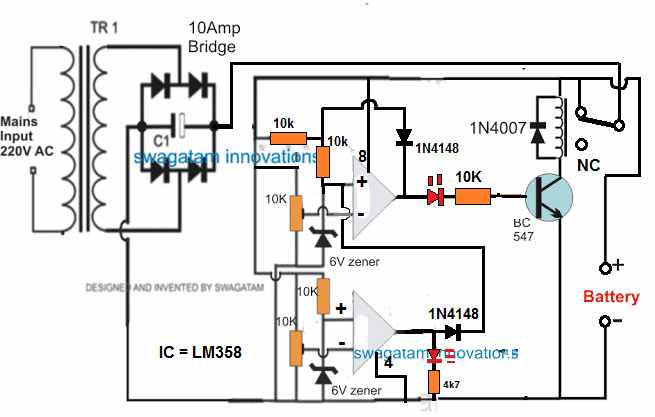
How it Works
Assuming there's no battery connected, the relay contact is at N/C position. Therefore when power is switched ON, the op amp circuit is unable to get powered and stays inactive.
Now, suppose a discharged battery is connected across the indicated point, the op amp circuit gets powered through the battery. Since the battery is at a discharged level, it creates a low potential at (-) input of the upper op amp, which may be less than the (+) pin.
Due to this, the upper op amp output goes high. The transistor and the relay activate, and the relay contacts moves from N/C to N/O. This now connects the battery with the input power supply, and it begins charging.
Once the battery is fully charged, the potential at (-) pin of the upper op amp becomes higher than its (+) input, causing the output pin of the upper op amp to go low. This instantly switches OFF the transistor and the relay.
The battery is now disconnected from the charging supply.
The 1N4148 diode across the (+) and the output of the upper op amp latches so that even if the battery begins dropping it has no effect on the relay condition.
However, suppose the battery is not removed from the charger terminals, and a load is connected to it so that it begins discharging.
When the battery discharges below the desired lower level, the potential at pin (-) of the lower op amp goes lower than its (+) input pin.
This instantly causes the output of the lower op amp to go high, which hits the pin3 of the upper op amp. This instantly breaks the latch, and switches ON the transistor and the relay to initiate the charging process yet again.
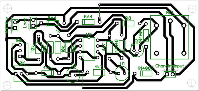
PCB Design
Adding a Current Control Stage
The above two designs can be upgraded with a current control by adding a MOSFET based current control module, as shown below:
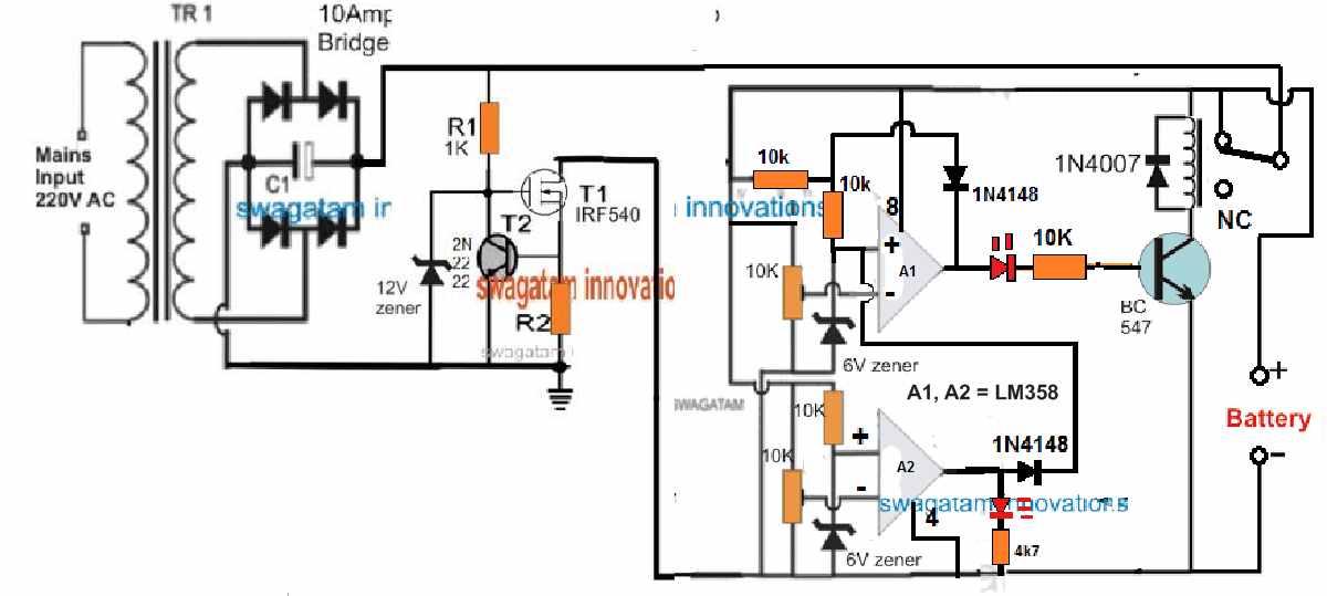
R2 = 0.6 / charging current
Adding a Reverse Polarity Protector
A reverse polarity protection can be included to the above designs by adding a diode in series with the positive terminal of the battery.
Cathode will go the battery positive terminal, and anode to the op amp positive line.
Please make sure connect a 100 Ohm resistor across this diode, otherwise the circuit will not initiate the charging process.
Removing the Relay
In the first auto cut off based battery charger design, it may be possible to eliminate the relay and operate the charging process through solid state transistors, as shown in the following diagram:
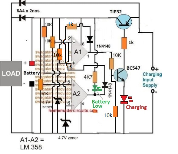
How the Circuit Works
- Let's assume A2 preset is adjusted at 10 V threshold, and A1 preset is adjusted at 14 V threshold.
- Suppose we connect a battery that is discharged at an intermediate stage of 11 V.
- At this voltage pin2 of A1 will be below its pin3 reference potential, as per the setting of the pin5 preset.
- This will cause the output pin1 of A1 to be high, turning ON the transistor BC547 and the TIP32.
- The battery will now start charging via TIP32, until is terminal voltage reaches 14 V.
- At 14 V, as per the setting of the upper preset, pin2 of A1 will go higher than its pin3, causing the output to turn low.
- This will instantly switch OFF the transistors, and stop the charging process.
- The above action will also latch the A1 op amp through the 1k/1N4148 so that even if the battery voltage drops to the SoC level of 13 V, the A1 will continue hold the pin1 output low.
- Next, as the battery begins discharging via an output load, its terminal voltage begins dropping, until it has dropped to 9.9 V.
- At this level, as per the setting of the lower preset, pin5 of A2 will drop below its pin6, causing its output pin7 to turn low.
- This low at pin7 of A2 will pull pin2 of A1 to almost 0 V, such that now pin3 of A1 becomes higher than its pin2.
- This will immediately break the A1 latch, and the output of A1 will once again turn high, enabling the transistor to switch ON and initiate the charging process.
- When the battery reaches 14 V, the process will repeat the cycle yet again
How Set the Presets
Initially keep the wiper arm of A1 preset to the ground level, and keep the wiper arm of the A2 preset at the positive supply level.
Take a variable power supply, adjust its voltage to the full charge level of the battery and connect the supply to the circuit from the "battery side" (not from the emitter side of TIP32).
You will see that the RED LED has illuminated.
Now, slowly adjust the A1 preset until the RED LED just shuts off.
The full charge cut off is now set.
After this, decrease the power supply voltage to a point which corresponds to the low discharged level of the battery at which the charging needs to be restarted.
Now adjust the A2 preset slowly until the Green LED and the RED LED both illuminate together.
Your low battery recharge level is now set.
That's all, now you can try testing the circuit on a real discharged battery, but this time make sure to connect the charging supply from the emitter side of TIP32.
Single Op amp Automatic Battery Charger Circuit
Automatic battery chargers just aren't economical, but the protection they provide from overcharging and potential battery degradation is extremely appealing.
The circuit illustrated here is meant to be a low-cost replacement to commercially available fully automated chargers.
The concept is to pick a basic battery charger and install an add-on module that will automatically check the condition of the battery and turn off the charge current as soon as the battery gets fully charged.
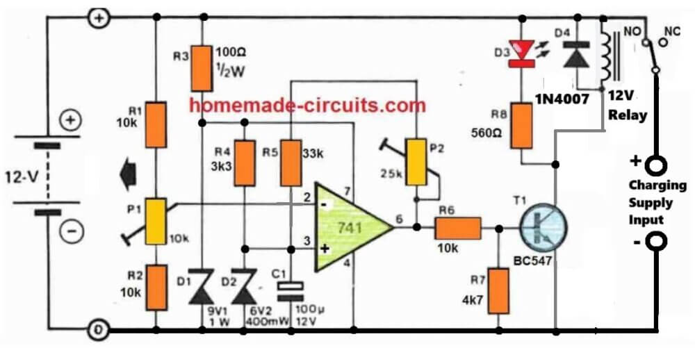
How it Works
The circuit is simply made up of a comparator that checks the battery voltage in relation to a preset reference value.
When the battery voltage surpasses a certain peak value, a relay is turned OFF, causing the charge current to be terminated. When the battery voltage declines below a certain specified lower limit, the relay activates, allowing the charge current to flow again.
A 741 op-amp serves as the comparator. The op-amp's supply voltage is stabilized by R3 and D1, thus it is immune to fluctuations in battery voltage.
The reference voltage, that is supplied to the op amp's non-inverting input through R4 and D2, is generated through this stabilized supply.
The reference voltage is compared with the battery charge voltage, via the resistive divider.
As the battery charges, the voltage at the inverting input of the op-amp finally becomes higher than that on the non-inverting input, causing the output of the op-amp to go low, switching off T1 and T2.
This causes the normally closed contact of the relay to open, cutting off the input charge current to the battery.
The battery full level will then illuminate LED D3 to show that it is completely charged.
A part of the op-amp output voltage is sent back to the inverting input through P2 and R5 to discourage the battery from reverting to the charging mode at the smallest reduction in the battery voltage.
The op-amp therefore works in the same way as a Schmitt trigger, with P2 determining the level of hysteresis, or the battery potential where the op-amp output can turn low again.
How to Setup
The easiest way to setup the circuit is to use a adjust stabilized voltage to simulate the battery voltage.
An input voltage of around 14.5 V is determined, and P1 is tuned so that the relay simply clicks off (opens).
The voltage of the 'battery' is then lowered to 12.4 V, and P2 is tweaked until the relay reconnects and switches ON. Because P1 and P2 will have an effect on each other, the operation should be done numerous times.


Questions & Answers
Very Usefull to all electronic hobbiests. Thanx from all hobbiests.
it's my pleasure
Hello sir Swagatam Majumdar
I am a big fan of your circuits and find them very helpful. I have been viewing all of your circuits for long long time now.
How ever Please can you help me on this circuit. I have built it and connected everything correctly! how ever, You did not mention how to set up the cut off limits. I need to know how to set the turn on voltage for charging and the cut off voltage for when it is full. how do you adjust the 10K preset pots to your desired voltage values..??
kind Regards Darren
Thank you Darren, I appreciate your enthusiasm.
for the above circuit you just have to set the lower preset to get a high at the output of the lower voltage, this must be done for the lower voltage threshold of the battery.
Similarly the upper preset should be adjusted to get a high at the output of the upper opamp, and this must be done for the higher threshold or the full charge threshold of the battery.
Once the above adjustments are done , the circuit can e expected to work automatically and produce the proposed cut off functions.
can the input supply be a solar panel? is this a monitor for batteries or a charger with battery monitor?
it will work with solar panel input, and monitor the cut-offs with battery alone or with an input
Sorry dear i am so excited from your blog dear I have one more problem
I have required a boost controller of gprs data logger which have 1A load at the time of network searching or data transmission for 10ms than normal on 50ma sleepmode current is 600uma
In put 2 to 3.6 volt from lithium primary call with 250ma output
Output constant 4v 1A
Due to long life period of battery it must to self cunsuption of circuit is lower qucent current
I founded a circuit of LTC3125 but this ic is not Easley available
So that suggest any easy circuit according to availability of spare and lower self consumption
Thank
Awaiting your response friend
If you like send me your whatsapp no
Gajendra 9414134388
Thanks Dear, I appreciate your response!
The input current should be at least 1.2 Amps….you cannot get 1amp output from a 250ma input
To get 4V constant from a 2 to 4V input I think you could use joule thief concept, as shown in the following figure:
https://www.homemade-circuits.com/2012/10/1-watt-led-driver-using-joule-thief.html
use 10 turns for both the winding instead of the shown 20 turns and 0.6mm wire thickness
the 4V constant can be achieved using a emitter follower voltage regulator buffer
Can it solve issue of low self consumption
No, there will be always some minimum consumption by the circuit….around 5mA when there's no input supply
Please clear i can understand "the 4V constant can be achieved using a emitter follower voltage regulator buffer"
at the output of the joule thief circuit you will need to connect the following type of circuit for achieving 4V constant…by using a 4.7V zener at the base:
https://www.homemade-circuits.com/2012/08/simplest-dc-cell-phone-charger-circuit.html
Hi Swagatam
Interesting circuit. However, I think the value of the feedback resistor should be 100K instead of 10K. What do you say?
BTW, have you tested this circuit?
Hi Abu Hafss, the low value resistor is purposely selected to hard latch the upper opamp when it detects the full charge threshold….the delatching operation of this opamp is done by the lower opamp output when the battery reaches the lower threshold.
hi swagatam
when testing your circuit we find setting A2 does not set the bottom limit for switching the relay but only for the led
Hi mars, remove the 1N4148 anode from the hysteresis resistor and connect it directly to pin#3 of the upper opamp and check the response…
working better but circuit is unstable
No, that shouldn't happen, opamps are extremely straightforward components, and moreover the preset adjustments are wide apart so instability cannot happen…connect LEDs across the opamp outputs to check the responses during their switching
hi
the circuit is running now but it does not like the 1n4148 connection
then how will the lower cut-off work…..that's not possible, I think your opamps are not good.
after testing the circuit i find the zeners to be losing about 1v as it is only getting about 1 ma with the 10k resisters
when adjusting the 10k resistors for about 10ma it is much more stable and is almost working at the zener voltage
the zener is for creating a fix reference level for the opamps, and 10K will not affect this functionality in any manner….
Hi Swagatam,
Thanks for nice Circuits. I need circuit idea to lighting the EXIT sign board with below requirement. Will you be able to help me ?
1) When AC main is there light should lit from AC->DC transformer same time it should charge 6V/12V battery and shut charging automatically when battery is full.
2) When AC mains is not there then EXIT sign light should lit using battery. Again load (light) should be disconnected when low battery.
Your circuit solves this problem. In this circuit relay is used, i think relay will consume battery current so i want MOSFET and Transistor to be used instead relay. I will use MOSFET or transistor which is cheaper and available with me so I am asking MOSFET as well as transistor.
Hope there is not much changes to be done to circuit.
3) In relay / MOSFET / Transistor which is less current consuming ?
Thanks for great, simple and effective circuits.
-Raghavendra
Hi Raghavendra, yes the above circuit will be quite suitable for your application.
A relay will consume some current but it will be negligible in comparison to the load current, but if you don't want this you can remove the relay and replace the BC547 transistor with a P channel mosfet and connect the battery across its drain and the negative line of the circuit.
the load may be connected via another mosfet (N channel), whose gate may be connected with the output of the lower opamp, source with the negative line and the load across its drain and the powitive line of the battery
mosfet and BJT both will consume no idle current, only a relay will consume some current while it's in the triggered mode.
Hi Swagatam, would you please clarifying more about replacing the relay and BC547. the BC547 your referring to in the circuit is the 2N222 if im not mistaken?
Also as P or N mosfet Chanel they both has, Drain, Gate, and Source.
I'm confused with both on how to connected with the above circuit.
Thank you.
yes that's correct, I am actually referring to the 2N2222.
the mosfet connections are explained in the previous comment…sketch the diagram according to the instructions and you will be able to get the idea
hi MR. Swagatam,
Thank you very much for the post and the circuit is great. I have a question, is it possible to switch the SPDT relay with a digital switch, as relays aren't really reliable?
thank you.
Hi Mamdouh,
relays are very reliable devices, but if you don't refer a relay you can use a mosfet, as explained in the above comment.
Also, what is the value of 6A4 ?
6A4 = 6 amp rectifier diode
yes it is a 6A4 diode in the image, and it will handle upto 4 amps easily and can be used for the above explained circuit
also, this circuit will work with 24V battery ?
and if so, i'm little confused about the calculation of the 10K variable resisters
let say my output source is 24V what is my pre-set for the variables 10K ?
also the output to the load need to be constant at 3Amp with 24V
would i be able to keep it at 3Amp with 24V at the output, and what kind of voltage at the external power do i need?
this circuit can be used with a 24V battery (and a 28V input)
the resistor values need not be changed.
for acquiring a constant voltage you can include a LM338 circuit as shown in the following article and in series with the load
https://www.homemade-circuits.com/2013/06/universal-high-watt-led-current-limiter.html
thanks for responding,
i was referring to the 10K resister that is connected to pin 3/5 on A1/A2
those resistors suppose to have 3 pins? if so are they variable resistors and im just gonna keep them at 10K for the sake of having 3 pins resistors.
sorry it might be a stupid question, but im trying to understand as well as learn.
thank you.
does it makes any difference with Lm338 or Lm338T?
No difference according to me
thanks for responding,
i was referring to the 10K resister that is connected to pin 3/5 on A1/A2
those resistors suppose to have 3 pins? if so are they variable resistors and im just gonna keep them at 10K for the sake of having 3 pins resistors.
sorry it might be a stupid question, but im trying to understand as well as learn.
thank you.
those are presets or trimpots, they are variable resistors, their values are suggested to be 10K, meaning the resistance is variable from 0 to 10k
is the 1k resistor on pin 1 not suppose to be the pull up resistor to the pos rail
No, it is correctly configured as indicated in the diagram.
If i use two 12V 7Ah battery in parallel, can i use 12 volt 5A smps to charge the battery and do i want make changes in circuit
5 amp can be a little high, it must not be higher than 3 amp…you can add a 24V automotive lamp in series or use a 5 ohm 5 watt resistor in series.
the smps voltage must be 14.5V…12V will not do…no other changes would be required
hi swagatam
after playing around with these battery chargers for a while i find that these opamp based chargers that checks the voltage and not the current moves from 12.6 to 14.4 very quickly and the opamp switches on and off but it is not really charging the battery as it only checks the volts
do you see the same and is there a remedy for better charging
Mars, opamps are not responsible for charging the battery, these are just sensors that are supposed to sense the battery voltage at the specified levels and initiate the cut-offs. The actual charging is done by the power supply source whose voltage and current must be correctly rated…for lead acid battery this must be set at 14.4V and current at 1/10th of batt AH.
With the above rate the battery should take 10 to 14 hours to get fully charged….if this not happening then either the power supply could be malfunctioning or the battery could be faulty.
The opamp based chargers are more than perfect with their jobs….voltage detection is the right way to go for making automatic battery chargers.
what would you say is a good setting for the on and off time when charging a 12v battery at 14.4 volts
preferably charging should be switched off at 14.4V and restored at 11V
how would that work when most batteries are full at 13.8v and can not even reach 14.4v for cut off and completely discharged at 11.9v and going down below 50% which is 12.2v will damage the battery
all good batteries will reach the 14.4V mark, if not then the problem could be with the battery, and in that case the upper regulation would become meaningless since the battery itself is unresponsive above 13.8V.
The lowest discharge level is 10V but ideally it should not be below 11V.
at 11.9V the battery can be considered healthy with its charge capacity
hi swagatam
just wondering why you always use opamps for the chargers and not a proper comparator like the LM 311 or the LM 393 and what is the purpose of the 1K resister on pin 1 is the 10K not enough for the histeresis