A field strength meter is an electronic device which is used for detecting and measuring the RF radiation generated from any RF transmitter circuit.
As we all know that transmitter circuits invariably use an inductor/capacitor based LC resonating circuit, also called the tank circuit, which oscillates at a specified resonating frequency to transmit the frequency in the air with an optimum power.
A field strength meter picks up this frequency radiation from the transmitters LC antenna network, and displays its strength or power through the attached meter.
Using an FET
The first field strength meter circuit below can work with any frequency as high as 250 MHz, or perhaps even more if needed.
Radio frequency energy is sensed by a short whip, rod, telescopic or other antenna, and the signal is rectified by diode D1 which gives a positive voltage for the FET gate across R1.
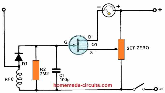
Because this FET is solely used as a DC amplifier, a 2N3819 or some other general-purpose transistor will suffice. The "Set Zero" potentiometer can be anywhere between 1k and 10k.
When there is no RF signal present, the gate/source potential can be adjusted such that the meter only indicates a tiny current.
In the presence of an RF field this current slowly grows in proportion to the intensity of the RF signal, which is indicated on the meter.
A 100uA metre may be used for increased sensitivity. An ammeter with a lesser sensitivity, for example like 250uA, 500uA, or 1mA, can also be utilized and might provide you with adequate information in most cases.
A VHF choke RFC can be used if the field strength metre is exclusively used with VHF. On the other hand, a short wave RFC choke will be most appropriate for regular use with lower frequencies.
Another Simple Field Strength Meter Design using a BJT
Another simple, and tested field strength meter circuit that allows model RC fliers to confirm that their remote control transmitter is indeed transmitting.
Any concerns about whether a problem is in the receiver or transmitter are immediately cleared up. The circuit's single active component is a transistor which serves like a regulated resistance in one of the bridge's arms of the meter.
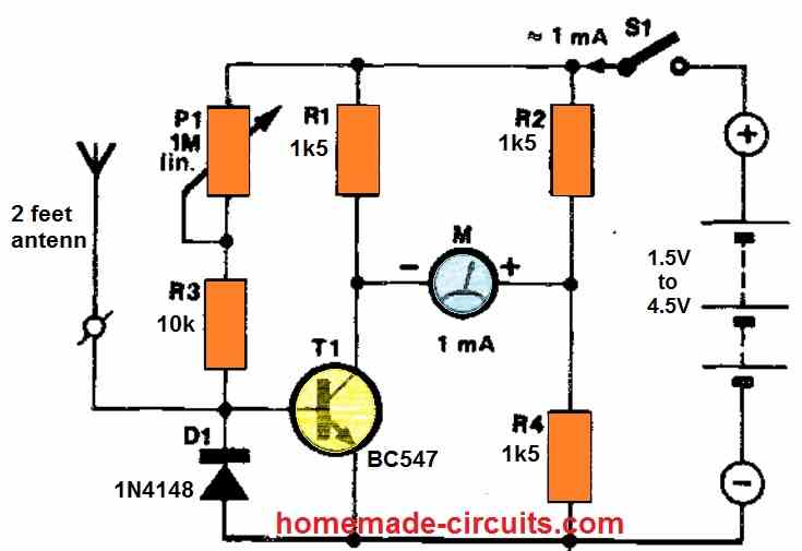
The antenna wire which is a telescopic type antenna is attached to the transistor's base.
As the HF voltage at the base of the antenna rises, the transistor is driven out of balance, causing the bridge to collapse.
The current subsequently passes via R2, the mA meter, and the transistor's collector-emitter junction, indicating the field strength on the meter.
Before turning on the transmitter for the testing, make sure that the meter needle us carefully adjusted to zero mark, using P1.
Transmitter RF Output Power Equation
The electric field strength generated by a transmitter with an isotropic radiator could be easily computed in an idealized free space.
The following formula works well for determining the field strength emitted from a transmitter LC circuit:
E ≈ √30 x P / d
Here, the electric field strength, E, is measured in volts per metre.
The transmitter power output in watts is denoted by P.
d represents the distance in metres from the radiator.
The parameter √30 represents the approximate value of √Z0/4π
where Z0 denotes impedance value of the free space, which is equal to 119.9169832 πΩ
The spacing between the transmitter and the receiver is clearly inversely related to the intensity of the electric field.
This relationship, unfortunately, is unsuitable for estimating the field strength generated by ground transmitters, because reflections and attenuation induced by structures in the vicinity of the transmitter or receiver can heavily impact the electrical field strength.
Simplest Field Strength Meter using a Buzzer
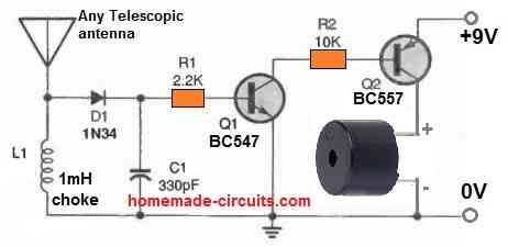
The field strength metre circuit shown above may be used to tune an antenna or a transmitter.
The transmitted RF is captured by a 24 inch pull-up telescopic antenna, rectified by a 1N34 germanium diode (D1), and then indicated by a piezo buzzer.
Changes in the antenna's length can be made to alter sensitivity.
You can also use OA79 diode instead of 1N34.
Field Strength Meter for 433 MHz Frequency
The circuit diagram of the 433 MHz field meter is shown in the following figure.
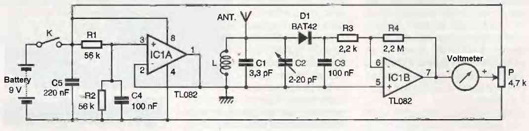
Its antenna leads to the tuned circuit composed of the inductor L, capacitors C1, C2, tuned to a frequency of 433 MHz.
The RF voltage present at the terminals of this tuned circuit is rectified by diode D1, which is in turn charged by capacitor C3, from which a DC voltage is obtained equal to the peak RF voltage (minus the threshold voltage of diode D1).
Since the amplitude of the received signals is generally quite low, it is advantageous to have the lowest possible threshold voltage for diode D1.
That is why it is necessary to use a Schottky diode (with a conduction threshold of around 0.2V) instead of a silicon diode (with a threshold of 0.6V).
The energy stored in C3 is not directly usable by the indicator voltmeter, so an impedance matching and significant voltage amplification (R4/R3 = 1000) are performed using the operational amplifier IC1b, which is wired as an inverting amplifier.
The voltmeter is connected to the output of the operational amplifier on one hand and to the wiper of potentiometer P on the other hand.
With this connection arrangement, it is possible to simultaneously adjust the overall sensitivity of the circuit and compensate for the presence of any offset voltage at the IC1b level.
For IC1b to function properly, this circuit requires a symmetrical power supply with respect to ground.
The second operational amplifier within the IC1 package converts the asymmetrical 9V voltage (supplied by the battery powering the circuit) into symmetrical +4.5V and -4.5V voltages with respect to the ground point.
This symmetrization is achieved by biasing the non-inverting input of IC1a at half the voltage supplied by the battery (using the voltage divider R1, R2, decoupled by C4).
Since IC1a is wired as a buffer amplifier, its output has the same potential as its non-inverting input but with a low impedance. This intermediate potential serves as the ground reference for the circuit.
How to Use
Set the wiper of potentiometer P to the midpoint and remove any source of RF emission at 433 MHz. Power up the circuit and verify that the voltmeter shows no deviation.
If that's not the case, adjust the setting of P until there is no deviation.
To tune the input circuit to the frequency of 433 MHz (adjusted by C2), it is necessary to have a small transmitter operating at this frequency in close proximity to the field meter (a few centimeters away).
It is not necessary for the transmitter to have an external antenna, but if it does, both antennas should be close to each other.
With both circuits powered, you should observe that the voltmeter needle deviates more as the distance between the transmitter and the field meter decreases.
If the voltmeter needle reaches its limit, you can either adjust the setting of P or slightly move the transmitter away (preferred solution).
While ensuring that the distance between the transmitter and the field meter remains constant, adjust C2 so that the voltmeter deviation is maximum.
It is strongly recommended to use an insulated adjustment screwdriver to avoid any hand effects during this adjustment.
If the needle reaches its limit during the adjustment, move the two devices apart, if possible, so that the observed maximum for the optimal C2 setting corresponds to approximately 75% of the voltmeter scale.
Although the field meter should theoretically be operational after this adjustment, you can try to improve its sensitivity by adjusting its receiving antenna.
To do this, place the field meter at a distance from the transmitter such that the voltmeter deviation is close to 50% of the maximum deviation.
Then, shorten the length of the field meter's antenna by 2 or 3 mm and adjust C2 to obtain a new theoretical maximum that is higher than the previous one.
If that's not the case, do not modify the antenna length any further.
However, if a higher maximum is observed, try reducing the antenna length by 2 or 3 mm again until the observed maximum is equal to or lower than the previous one.
Ensure that the distance between the two devices involved in this adjustment (transmitter and field meter) remains constant throughout this operation.
Passive Field Strength Meter Circuit
This untuned, unpowered field strength meter may be used to test the performance of handheld transceivers, antennas, radio control equipment, and other antenna systems.
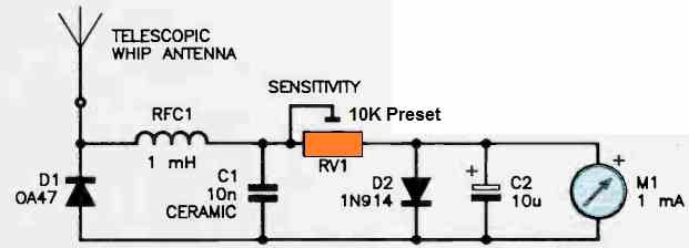
The telescopic whip antenna's signals are rectified using the germanium diode 0A47. RFC1 blocks the RF in positive-going half-wave pulses, and C1 drives current via RV1 and the meter while also blocking the RF.
C2 evens out modulation variances, whereas D2 stops powerful signals from knocking the meter.
Changing RV1 alters the circuit's sensitivity.
The meter could be installed easily on the front of an appropriate casing, having the telescopic whip attached on top, or anywhere is appropriate for the desired application[s].
To get excellent results at the upper frequencies, maintain the connections between D1, RFC1, and C1 short. Remember that a high brightness LED could be used in the place of D2.
Highly Sensitive Field Strength Meter Circuit
This field strength meter performs effectively at frequencies ranging from extremely low to very high. A short telescoping whip serves in place of the pickup antenna.
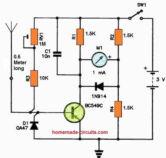
D1 half-wave rectifies the signals, and the resulting positive pulses are delivered to the base of Q1. Q1 has a little amount of bias generated through RV1-R3.
The transistor's collector-emitter and resistor R4 constitute two of the bridge's arms, with resistors R1 and R2 creating the remaining two arms.
The bridge becomes unbalanced when current passes through R1, the transistor's collector, and into the meter.
By altering the base current, RV1 resets the meter. The rectified RF at the transistor's collector is blocked by the capacitor C1. The meter needle is restricted from smashing hard, thanks to the diode across it.
This extremely sensitive field strength meter circuit may be powered by a single 3 V battery. For the best sensitivity, D1 is a germanium diode; however, an everyday silicon diode, such as a 1N914 or 1N4148, will work with minor sensitivity loss on weak signal levels.


Questions & Answers
I know we are dealing with rf frequency, can l use any general purpose transistor or l should take the transition frequency inconsideration for the diode.
You can use a BC547 transistor which is a general purpose transistor having an operating frequency higher than 200 MHz. 2N2222 will also work, or any other similar. If the sensing frequency is higher than 200 MHz then you may have to consider using some other appropriately rated transistor.
Thanks for your reply, the problem am encountering is getting these diodes with low forward drop voltage. Is it true that you can configure a transistor to work as a diode with a low forward drop voltage, if true ,show me how and which types of transistors to use. Thanks Andrew
A normal silicon transistor can be used for making a diode but it will also drop around 0.6V just like a diode. You may need a germanium transistor for this, which will drop not more than 0.2V
How can a variable frequency field strength meter be constructed
In the following example you can use the C2 capacitor to vary the sensing frequency:

I noticed that you always answer the readers’ questions. My question is: How can I check if the 2.4Ghz remote control from a remote controlled toy car is emitting? I would like to make a Simple Field Strength Meter Circuit. I want to specify that the remote control can emit in 4 frequency bands around 2.4MHz. What scheme do you recommend? Thank you.
Thank you for your question. 2.4MHz is a very high frequency and making the LC tank circuit that would resonate with this frequency can be quite challenging. If you can optimize the LC tank network of the field strength detector to resonate at this frequency then definitely the circuit will be able to respond to this frequency and detect it
Hi… Just stumbled on your website while searching Google.I’m looking forward to building one of your rf Field Strength Meter circuits. You seem to have a good selection of circuit schematics with a very nice explaination of how the circuits work. Hoping to see more soon.
Hi, Thank you very much, and glad you liked the post. You can definitely try one of these circuits, although these were not designed by me.