• Skip to main content
  • Skip to primary sidebar

Homemade Circuit Projects

Need circuit help? Post them in the comments! I've answered over 50,000!

Blog | Categories | About | Hire Me | Contact | Calculators-online
You are here: Home / Sensors and Detectors / Mobile Signal Vibrator Circuit


Mobile Signal Vibrator Circuit

Last Updated on May 18, 2023 by Swagatam 4 Comments

This mobile signal vibrator circuit will detect the wireless high frequency signals from your mobile phone and will activate the connected vibrator motor. This circuit can be used for many different customized applications.

Table of Contents
  • Circuit Description
    • Construction

While the implementation of an external vibrator is not electronically complicated, it encounters a simple mechanical problem with the vibrator. How can we reproduce the characteristic and highly perceptible vibrations of "real" portable vibrators?

It's quite simple, just use a motor whose output shaft is connected to an unbalanced weight, meaning an asymmetrical piece that causes significant vibrations when it rotates.

Unfortunately, if you try to make such a component yourself, it is generally heavy, bulky, and consumes too much power to be sustained for a sufficient duration by batteries.

However, fortunately ready made vibrator motors are quite easily available nowadays from the market.

Circuit Description

Creating a vibrator with this motor has been a rewarding endeavor for us.

It is important to know that when your mobile phone receives a call, it transitions from standby mode to active mode.

In response to the call, it sends several bursts of digital data at its maximum power, which is still 2W.

The power of transmission may vary depending on the reception conditions of the relay for your communication, but its initial power is sufficient to trigger the circuit, as shown in Figure 1 below.
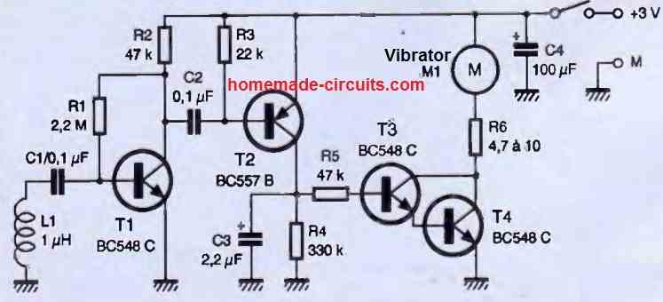
The L1 coil, which is a standard off-the-shelf component, intercepts part of the signal of the phone during its initial response to the received call, meaning when it needs to activate the vibrator.

This very weak voltage is greatly amplified by T1, and the pulses present on its collector are of sufficient amplitude to turn on T2.

T2 then rapidly charges capacitor C3, which can only discharge through R1 and the base-emitter junction of the T3/T4 pair.

These two transistors are connected in a configuration called a "Darlington pair," which is equivalent to a single transistor with a gain equal to the product of the gains of the two transistors used.

Therefore, if we use BC548C transistors here, whose minimum gain is 400, we effectively create a "super" transistor with a gain of 160,000!

This Darlington pair conducts current when the voltage across C3 exceeds approximately 1.4V, and the vibrator motor is then powered.

Since our circuit operates at 3V, we have included a current-limiting resistor R6 to prevent damaging the motor, which, as a reminder, is designed for a nominal voltage of 1.3V.

Construction

Except for the vibrator motor, all the other components are common and can be found anywhere. The printed circuit board (PCB) we propose is shown in the following figures.

It is small enough to fit in a case that won't take up much space in your pocket alongside your mobile phone.
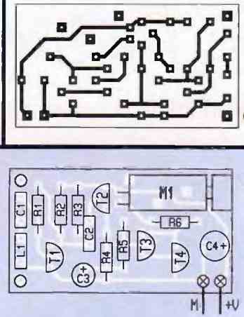
The component placement is straightforward and is indicated in the figure above. Start with the passive components and finish with the semiconductors and the motor.

Pay attention to the polarity of the components and make sure to connect the motor with its red wire to the positive power supply. The power supply should be at 3V.

As for the case in which you will place your circuit, you can use two R3 1.5V batteries, silver oxide button cells also rated at 1.5V, or a single lithium battery (such as CR2032) with a nominal voltage of 3V.

An on/off switch should be included because even though the circuit's idle power consumption is very low, reaching only 900uA, it will still unnecessarily drain the batteries.

The circuit operates immediately if no wiring errors have been made. Simply place it a few centimeters away from your mobile phone and make a call to observe the vibrator activating within a second of receiving the call.

The vibrator stops as soon as the phone stops ringing. The duration of the vibrator's activation also depends on the exact value of capacitor C3.

If you find the duration too long, you can reduce it by slightly decreasing the value of resistor R4.

You can also adjust the value of resistor R6, which can be between 4.7 and 10 ohms, according to your preference.

A lower value will make the motor spin faster, resulting in more pronounced vibrations.

In our experience, a value of 10 ohms provided satisfactory results while ensuring a long lifespan for the motor, as it is not excessively stressed.

You'll also like:

  • How to Build a Rain Sensor Circuit
  • noncontactcabletracercircuitNon-Contact Cable Tracer Circuit
  • P 20160629 080416Interfacing DHTxx Temperature Humidity Sensor with Arduino
  • Simple LDR Motion Detector Alarm Circuit

Filed Under: Sensors and Detectors Tagged With: Mobile, Signal, Vibrator

About Swagatam

I am an electronics engineer and doing practical hands-on work from more than 15 years now. Building real circuits, testing them and also making PCB layouts by myself. I really love doing all these things like inventing something new, designing electronics and also helping other people like hobby guys who want to make their own cool circuits at home.

And that is the main reason why I started this website homemade-circuits.com, to share different types of circuit ideas..

If you are having any kind of doubt or question related to circuits then just write down your question in the comment box below, I am like always checking, so I guarantee I will reply you for sure!


Previous Post: « AC 220V Over Current Monitor and Cut OFF Circuit
Next Post: High Efficiency Solar Charger Circuits using Switching Regulators »

Reader Interactions

Questions & Answers

Total Posts: 4
Newest Oldest
Ben Dover
March 22, 2024 • 3 years ago #150655

Hi
If you were to simulate this circut in ORCAD etc. How would you simulate the Antenna part ( L and C1)
Could you just replace it with a Sinus wave former tuned to the resonace frequency. Im trying to figure out what the minimal signal strenght is for the whole circut for it to work

Reply
SwagatamAdmin
March 22, 2024 • 3 years ago #150662

Hi, sorry, I am not good with simulator softwares so have no idea how to solve the issue.

Reply
Ben Dover
March 25, 2024 • 2 years ago #150844

Hi again Thx for prevoius answer
Btw
How did you end up with the values of C1 and L. Arent mobile phones using a much higher frequency?

Reply
SwagatamAdmin
March 26, 2024 • 2 years ago #150896

In the above design, the L1 is detecting the leaking RF power of the mobile network, so the frequency is not relevant here.
And there is no LC tank circuit or resonance necessary for this circuit.
C1 acts like a blocking capacitor, not a resonance capacitor.

Reply

Need Help? Please Leave a Comment! We value your input—Kindly keep it relevant to the above topic! Cancel reply

Your email address will not be published. Required fields are marked *

Primary Sidebar

My YouTube Channel

Circuit Simulator: Draw and Simulate Schematics

circuit simulator image


Categories

  • Arduino Projects (95)
  • Audio and Amplifier Projects (134)
  • Automation Projects (18)
  • Automobile Electronics (104)
  • Battery Charger Circuits (90)
  • Datasheets and Components (109)
  • Electronics Theory (151)
  • Energy from Magnets and Earth (43)
  • Games and Sports Projects (11)
  • Grid and 3-Phase (20)
  • Health related Projects (27)
  • Home Electrical Circuits (13)
  • Indicator Circuits (16)
  • Inverter Circuits (98)
  • Lamps and Lights (161)
  • Meters and Testers (72)
  • Mini Projects (28)
  • Motor Controller (68)
  • Oscillator Circuits (30)
  • Pets and Pests (15)
  • Power Supply Circuits (91)
  • Remote Control Circuits (50)
  • Security and Alarm (65)
  • Sensors and Detectors (107)
  • SMPS and Converters (46)
  • Solar Controller Circuits (62)
  • Temperature Controllers (44)
  • Timer and Delay Relay (51)
  • Voltage Control and Protection (44)
  • Water Controller (37)
  • Wireless Circuits (31)


Subscribe to get New Circuits in your Email


Other Links

  • Privacy Policy
  • Cookie Policy
  • Disclaimer
  • Copyright
  • Videos
  • Sitemap

People also Search

555 Circuits | 741 Circuits | LM324 Circuits | LM338 Circuits | 4017 Circuits | Ultrasonic Projects | SMPS Projects | Christmas Projects | MOSFETs | Radio Circuits | Laser Circuits | PIR Projects |


Recent Comments

  • Swagatam on Adjustable Voltage Regulator Circuit using LM324 IC with Over Current Protection
  • Swagatam on Inverter Circuit with Feedback Control
  • Swagatam on Inverter Circuit with Feedback Control
  • Swagatam on Proximity Detector IC CS209A Pinouts – Datasheet Explained
  • PRAFUL WANDHARE on Proximity Detector IC CS209A Pinouts – Datasheet Explained

Social Profiles

  • Twitter
  • YouTube
  • Instagram
  • Pinterest
  • My Facebook-Page
  • Stack Exchange
  • Linkedin

Calculators

  • ZVS Induction Heater + Tank Calculator Tool
  • Zener Diode Calculator
  • Wire Current and Thickness Calculator (Ampacity Calculator)
  • Voltage Divider Calculator
  • Transistor Base Resistor Calculator
  • Transistor Astable Multivibrator Calculator
  • TL431 Calculator
  • Solar Panel, Inverter, Battery Calculator
  • Ferrite Core Air Gap Calculator Tool
  • Parallel MOSFET Calculator Tool: How to Connect MOSFETs in Parallel Safely
  • LC Resonance Calculator for EV Battery Charger Circuits
  • LED String Series Resistor Calculator
  • PFC (Power Factor Correction) Calculator Tool: 3kW
  • Passive Power Factor Correction (PFC) Calculator
  • LM567 IC Calculator Tool
  • SMPS Flyback Boost Converter Calculator
  • Shunt Resistor Calculator for Ammeters
  • SCR and Triac Gate Resistor Calculator
  • Battery Back up Time Calculator
  • Boost Converter Calculator (Non-Isolated)
  • Bootstrap Capacitor Calculator
  • Buck Converter Calculator
  • Buck-Boost Converter Calculator
  • Capacitance Reactance Calculator
  • DCM Flyback Transformer & Wire Gauge Wire Size Calculator Tool
  • Filter Capacitor Calculator
  • IC 4047 Calculator (Frequency and PWM)
  • IC 4060 Calculator
  • IC 555 Astable Calculator
  • IC 555 Monostable Calculator
  • IC SG3525, SG3524 Calculator
  • Inductance Calculator
  • Induction Heater Inductor and Resonant Frequency Calculator
  • Induction Heater Work Coil Calculator
  • Inverter LC Filter Calculator
  • LC Resonance Calculator
  • LED Current Calculator
  • LM317, LM338, LM396 Calculator
  • NAND/NOT Gate RC Values Calculator
  • NOT, NAND Gate Frequency Calculator
  • Notch Filter Calculator Tool
  • Ohm’s Law Calculator
  • Phase Angle Phase Shift Calculator
  • Power Factor (PF) Calculator
  • RC Filter Calculator
  • Reactance Calculator
  • Sine Table Calculator for SPWM Arduino Code
  • Small Signal Transistor(BJT) and Diode Quick Datasheet
  • SMPS Calculator for Toroidal Ferrite Transformers
  • SMPS Flyback Transformer Calculator – Design by Target Duty Cycle
  • TL431 Calculator
  • Op-Amp Hysteresis Resistor Calculator

© 2026 · Swagatam Innovations