A Hi-Fi surround sound system (5.1) typically consists of 4 speakers at the corners of the room, and a center speaker just below or above the TV or the video system. This center speaker becomes the main speaker box of the surround sound since it is responsible for delivering the high quality voice output from the video audio, which gives a feeling of the voice coming straight from video itself.
In this article I have explained how to make one such Hi-Fi center speaker box which is technically known as the SC8, C80 due to its 80 mm 8 Ohm speaker units.
In surround sound home theater systems, the center channel refers to an audio channel common to many other variants of the surround sound. It is the channel mainly, or exclusively, devoted to reproducing the dialogue frequency of the audio/visual signal.
Main Features of Center Speaker Box
The speaker(s) employed for the center channel are specifically mounted at the center of the audio/video gadget and behind it, to create the illusion that voices from the middle channel is being generated from the picture screen itself. This center channel speaker is located over or below the video screen in most home surround sound systems.
The center channel also dominates the vocal sound area, removing ghost perceptions like those which are typically accompanied in quadraphonic sound system, when its speakers are not perfectly positioned
The central channel speaker system removes the need to create a "phantom center" with stereo speakers on the left and right. The center channel offers picture stabilizing effects and is known to be the most critical in videos production platform.
The center loudspeaker use magnetically shielded drive modules, that are mounted directly underneath the television/video/PC display. This is very crucial , or else the TV sound and vision would be seriously impacted.
A Complete Theater Like Sound using a Low Bandwidth
A full surround-sound installation comprises of the power amplifier(s), surround-sound decoder, the regular left-hand and right-hand channel loudspeakers, a central speaker positioned in the middle of these two channels, and a couple of rear speakers supplying the spatial information.
The main speakers needs to be be basically of hi-fi quality, because these essentially decide the ultimate sound level; and are typically powered by the external amplifier.
The center channel is mostly used for the voice frequency, and its output content consists of mostly the aggregate of the left and right channel signals from which the low frequencies get filtered. That's exactly why this speaker's frequency spectrum does not need to stretch to the extreme lower ranges. To put it another way, both the box and the drive units simply aren't required to be massive in size.
The rear speaker frequency response requires to be just around 100 Hz to 7 kHz, because this matches the decoder output frequency. The volume quality from these speakers is also fairly small compared to that from the other three speakers.
This suggests that the drive units could be compact, high-quality wide-band with their specs. The rear speaker power levels do not need to be large either, mostly because they do not need to produce the heavy low frequency signals. For nearly all cases, a 20 W rating is enough.
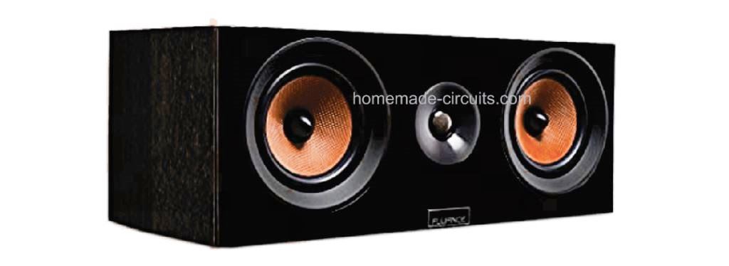
The Center 80 Speaker System
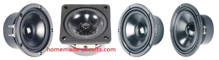
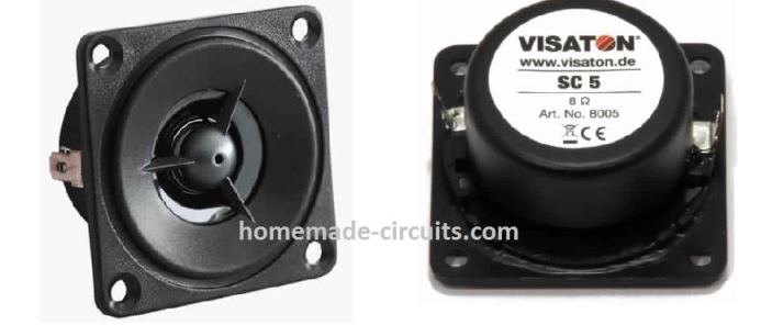
The center speaker employs a couple of 80 mm wideband drive units Type SC8 and a 10 mm tweeter Type SC5. These drive units are, as explained previously; shielded magnetically.
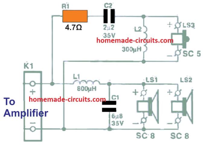
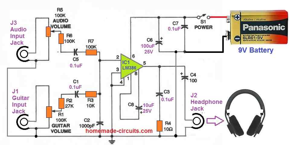
The shown circuit diagram of the filter circuit associated with the drive units, features a cross-over frequency of 5kHz and roll-offs frequency of 12 dB per octave.
As a result of the shielding, the speaker could be positioned very close to a TV receiver, computer monitor or the preferred audio/video system. Both 80 mm drive units are fitted at the lower half of the housing with the tweeter fitted above them.
In several loudspeakers, the tweeter is positioned in between the two wideband units (also named as d'Appolito construction), however this includes the disadvantage that the waveform of sound radiation frequencies close to the cross-over frequency deviates substantially within the vertical direction (assuming the speaker is vertically positioned).
Generally, this may not have much impact on the sound, yet because the loudspeaker in surround-sound applications can often be listened to in resting position, could mean that audio frequency varying while the listener is moving his/her head a bit across right or left... and this actually, may not be the ideal working of a surround sound.
In the proposed the construction this effect is simply eliminated, which means that sound stays homogeneous beyond the audible axis. The efficiency of the Center 80 could be examined through the frequency characteristic in Figure 2
Analyzing the Frequency Response of the Surround Sound Speakers
Notice that the minor bump at 150 Hz assures that the speaker, despite its humble sizes, generates a in-depth sound. The effect detailed in the last section thankfully would not take place in the rear speakers, because these only use just one 80 mm drive unit.
Despite their slim dimension, the speakers generate a fantastic spatial audio effect. As stated previously, they will reproduce the sound upwards. This creates excellent dispersing of the audio, and preclude the hot spot, very often experienced with other surround sound devices.
A hot spot is actually a specific area in a room where the sound seems to be in higher concentration, while it must, obviously, be equally spread out.
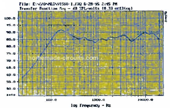
The overall performance (frequency response) of the speakers was assessed in a real test setup: the frequency response at a range of 1 m from each one, hanging over a wall at around 5 feet high, is demonstrated in Figure 3.
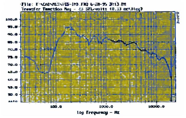
The roll-off at increased frequencies is triggered due to the basic reflections, as are indicated in the graph. The 'normal' frequency curve, measured while the speaker were positioned horizontally down and radiating sound straight into the test microphone direction, could be witnessed in Figure 4.
Making the Speaker Cabinet
The housing box for all 3 loudspeakers are quite effortlessly designed. Each one is made of 6 rectangle-shaped components of medium density chipboard, which any DIY suppliers can trim to size to suit your needs. The boards are glued with each other using appropriate damping materials. The building drawings are shown in Figure 5 below.
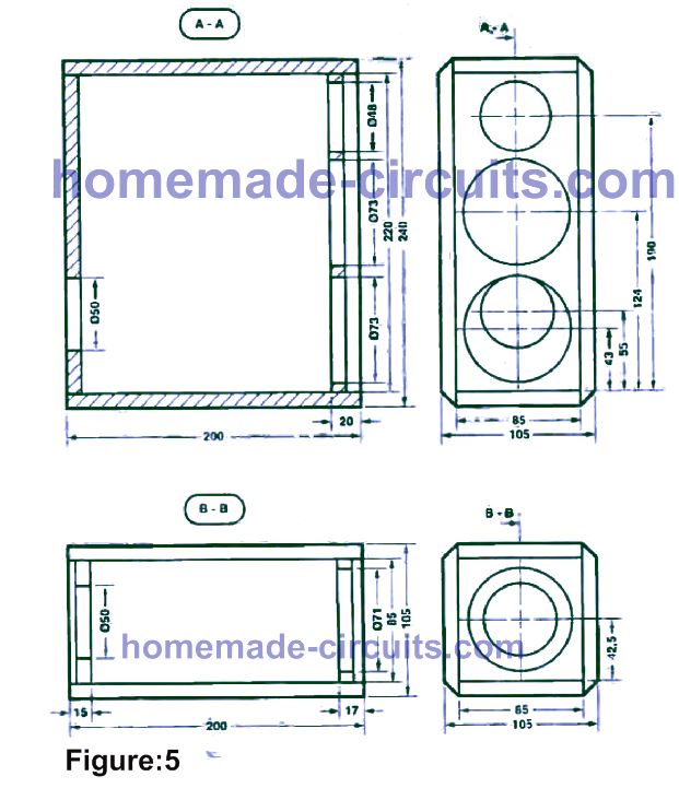
The drive units could be secured by steel netting or covers. The backside of each housing must have openings for the wire leads. A few users could find it far easier to slice these holes prior to the box is nailed together.
Ensure that the cross-over filter is as stream-lined as it can be, as there is very little space inside the central speaker box. A 15 mm hole could be chopped in one of the sides of the rear loudspeakers. This allows a handy means of suspending the speakers from your wall (with the drive unit directing towards the roof).
The speaker boxes could be given a finishing touch as per personal flavor. When everything is completed, the boxes could be wired up. Each box must subsequently be stuffed with an appropriate damping substance, for example polyester wool or anything similar.
Parts List
| Part | Details |
|---|---|
| Center: BO | |
| Crossover Filter | |
| R1 | 4.7 Ω, 5 W |
| C1 | 6.8 µF, 35 V, bipolar or polystyrene |
| C2 | 2.2 µF, 35 V, bipolar or polystyrene |
| L1 | 0.3 mH air-cored inductor, wound from 0.6 mm diameter enameled copper wire |
| L2 | 0.8 mH air-cored inductor, wound from 1 mm diameter enameled copper wire |
| Drive Units | |
| L1, L2 | 6 Ω, magnetically shielded wideband unit, Type SC8 (Visaton) |
| L3 | 8 Ω, magnetically shielded polycarbonate dome tweeter, Type SC5 (Visaton) |
| Chipboard | 10 mm thick medium density |
| Sheets | 2 sheets 85 × 220 mm (front and aft), 2 sheets 200 × 240 mm (sides), 2 sheets 85 × 200 mm (top/bottom) |
| Damping Material | Front grille for Center BO (Visaton), Loudspeaker terminal |
| Effect BO (Two Required) | |
| Drive Unit | LS = 8 Ω full-range driver, Type FRS8 (Visaton) |
| Chipboard | 10 mm thick medium density |
| Sheets | 2 sheets 105 × 200 mm (sides), 2 sheets 85 × 200 mm (sides), 2 sheets 85 × 200 mm (top and bottom) |
| Damping Material | Front grille for Effect BO (Visaton), Loudspeaker terminal |


Comments
Has anybody else noticed the box design does not match the picture?
Hey, the first image is not a prototype image, it is just for showing how the design might look…
Hi Swagatam,
I do not have instrument to read values for mH.
Can you kindly teach me how to wind the air core inductors for L1 = 0.3mH, and L2 = 0.8 mH for the crossover network of 50 Watts mini ground shaker amplifier? And what are the equivalent numbers for the magnet wires/varnished copper wires in SWG or AWG, and what diameter I will use as winding form / bobbin?
Thanks for your circuits, it will save me money for DIY builds.
Hi Egay, The mini ground shaker does not require a crossover network, it is specifically designed for high bass output just as we have in sub woofer amplifiers.