In this article I have explained a couple of very easy to build RF detector circuits, which can be used to sense or detect or sorts of Rf electrical noise that may be floating in the surrounding atmosphere.
What is RF
RF stands for radio frequency, which is a kind of electrical interference transmitted in the atmosphere, whenever there is a voltage/current fluctuations across an electrical system.
Whether it is a static electricity (DC) or a capacitively linked AC from neighboring overhead wires, noise spikes from engines, or a radio-frequency waves from a cellphone, all contribute to the world's electromagnetic interference and noise.
A RF noise can be a high level noise such as during thunderstorm lightning, welding, or very tiny such as when you click a gas lighter.
How can Electronic Circuits Detect RF
RF noise or RF signal can interfere with an electronic circuit working if it has a semiconductor with a high impedance end unconnected. Noise is picked up whenever such a high-impedance input is left open and disconnected.
This is actually a problem that an electronic can face due to RF interference, and this can cause its output to amplify the RF interference and cause a correspondingly fluctuating output voltage.
However, the above problem becomes the advantage of our RF detector circuits, and we used this to illuminate an LED whenever an RF interference is detected our circuit.
Using Transistors
As shown below a Darlington connection is used in our first RF detector circuit, using transistors in a super-high gain mode with a rather high input impedance.
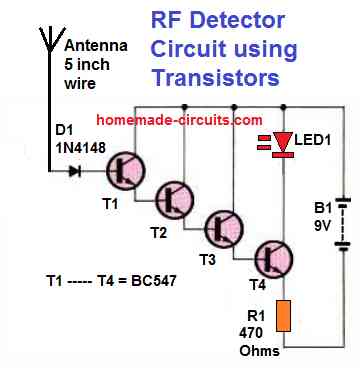
If each of the transistor in the diagram is assumed to have a current gain (β) of 150, the total β becomes 150 x 150 x 150 x 150 = 506250000 and the input impedance is potentially 506250000 x 470 ohms, or almost 237937500000 ohms or 237937.5 Mega Ohms.
Due to leakage, the above mentioned result might actually not be as high as it appears. In essence, the circuit's difficulty is that any RF signal in or near the first couple of transistors is substantially boosted. That's most likely why just a handful of your transistors can work effectively.
However, for this simple transistor RF detector to work a super clean, alcohol-washed veroboard would be required, under reduced humidity circumstances.
Temperature variations, light beaming on the transistor, and other inbound signals would almost certainly still trigger the circuit and could make it unstable.
Calculating Gain in Cascaded Transistor Configurations
As in the above RF circuit, when you have multiple transistors set up in a cascaded configuration it means that the overall gain of the system is actually the product of all those individual transistor gains working together.
But if we are talking about a straightforward RF detector like the one we have here it is important to note that the transistors are not really amplifying the RF signal in a full-on way.
Instead they are more like switches that react to the rectified signal they receive.
Because of this the gain we get is kind of limited and it really depends on how strong the RF signal is to begin with.
Now on top of that the effective gain we see is also affected by how the circuit is designed specifically as a detector. This means that in this case it is less about traditional amplification and more about how sensitive the circuit is to detecting signals.
The gain calculation for this type of circuit can be simplified to:
Gain ≈ β * (R1 / V_T)In this case, with R1 = 470 Ω and β ≈ 200:
Gain ≈ 200 * (470 / 0.026) ≈ 3,615,385.CMOS Circuit using IC 4001
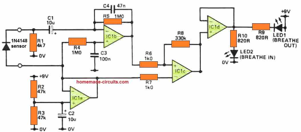
The next diagram below depicts another simplified RF detector circuit based on an IC that you might enjoy playing with.
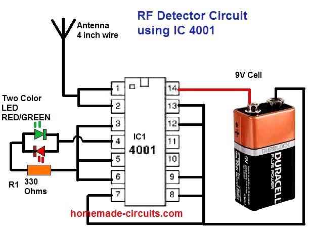
Touching or keeping your hand on top the antenna will flip the LED red to green, or opposite; it could also become yellow or orange, or even switch off completely.
All sorts of RF interference such as RF from mobile phones, thunder lightening, AC hum all can cause the LEDs to flicker in response to these interference.
The extraordinarily high input impedance of CMOS integrated circuits is used in this design. It also demonstrates why such a CMOS inputs must never be left disconnected; electrical noise can trigger highly unpredictable performance.
On dry seasons with an abundance of static electricity in the surrounding, you might expect to obtain the most fascinating results.
100 MHz RF Detector
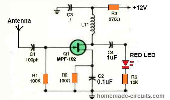
This circuit is capable of detecting signals up to 100 MHz, depending on the value of L1. In the circuit, the FET serves as a wideband amplifier.
You can select the coil as per given in the following table:
| Frequency Range | Suggested L1 Value | Type of Coil | Notes |
|---|---|---|---|
| 30 to 100 MHz | 1 µH to 5 µH | Air-core, 3–5 turns on 6 mm | Works best at VHF |
| 10 to 30 MHz | 10 µH to 50 µH | Ferrite or air core | Shortwave/HAM |
| 3 to 10 MHz | 100 µH to 220 µH | Ferrite core | Medium shortwave |
| Below 3 MHz | 470 µH to 1 mH | Ferrite, toroid | MW, LW bands |
These values are approximate values, exact value is not critical because this is not a tuned detector but values should avoid self-resonance near target frequency.

Questions & Answers
Hello, I know how to solder and repair some electronic devices, looking at your circuit to detect RF, how can I build or adapt these RF circuits to make a candle flame simulator?
Thank you.
Hi, can you please tell me how do you wish to use it as a candle flame simulator? Do you mean the LED flickering in response to RF signals must simulate a candle flame? In that case you can try the IC 4001 based circuit and check the response by bringing the antenna near AC mains 220V supply…
Hello, good afternoon. The circuit is very interesting, but I’ve done some tests and haven’t had the desired results. The question is, how many mH should the coil be for low frequencies? Around 60 Hz.
Hi, for low frequencies the last circuit is not suitable, I would instead recommend using the first two designs, or alternatively you can simply try the following concept:
https://www.homemade-circuits.com/bug-detector-circuit-rf-sniffer-circuit/
Comment/question on choke values for the 100 MHz RF Detector circuit:
The text states:”This circuit is capable of detecting signals up to 100 MHz, depending on the value of L1. Use a 100 µH choke for signals between 30 and 100 MHz, a 1000 µH choke for frequencies between 2 and 30 MHz, and a 2.5 µH choke for signals below 3 MHz.”
IT seems counterintuitive that the frequencies between 2 and 30 Mhz have a higher value (1000 µH) than the signals between 30 and 100 Mhz (100 µH) when using only a 2.5 µH choke for signals below 3Mhz. Is this possibly a typo – the 100 and 1000 are flip-flopped?
I’m planning to use this circuit to track down RFI interfering with my ham HF bands (spike ‘clicks’ that generate broadband ‘static’ across almost the HF and non-HF bands, and audio hisses in discrete groups of several KHz wide.)
Thanks for a very informative site with some interesting and useful circuits!
That’s correct! Thanks for correcting the mistake, I have now corrected the mistake through a table, at the bottom of the article. I hope the circuit works for your intended application.
Thanks to your reply to my question which directed me to this article, I feel like I am very close to understand certain phenomena that was bugging me for a while now. So it is my understanding that and ecig mod and an rf detecting circuit share more or less the same components and please correct me if I am wrong but I assume since the rf detection is essentially made by amplification using transistors, in theory a detection circuit can strenghten the signal of a signal source that is nearby maybe with some added components to the circuitry.
About a year ago, I have discovered that an ecig mod of mine have been tempered with. I noticed that it was constantly killing one of the two 18650 batteries it required for operation although it had a bms circuit. I have taken apart the unit and noticed that the batery that was constantly dying has been bypassed to a point in the circuit. I realised that the unit was somehow vibrating/oscilating and creating a very high pitch that I could barely hear. I remember having a relief as I took the batteries out and actually falling asleep within 10 minutes. I will be posting a picture as I recover the device but I am still very much interested if you know or heard about such a modification to a standart tempcontrol ecig mod box primarily using what is available on the board to induce such an effect. I also noted constant error production on iphone siri app as well bluetooth signal generation (the original device had no bluetooth or such). I would greatly appreciate anything regarding this, as I am very curious to find out what was going on back than. Regards.
Thank you for your interesting question!
It seems the device has been modified to generate powerful resonating oscillations, which is able to create strong frequency RF frequency waves in the atmosphere causing interfering signals with nearby devices and jamming them forcibly.
The strong frequency could be also affecting the brain causing the discomfort you are facing.
Yes, this is definitely possible.
The draining of the batteries quickly indicate that the modified jammer is using high battery power to generate the powerful high frequency waves in the atmosphere.
There is something I don’t understand. In the 1st circuit, only electrons are allowed to pass from T1 to the antenna. It seems impossible for electrons to come back from the antenna to the circuit. When the electrons gather in the antenna over time, is there no problem for the circuit to work and detect the radio waves? Where do the electrons accumulated in the antenna go? Shouldn’t the electrons be able to exit as easily as they enter the antenna? I did not understand how the circuit could work, since the electrons coming to the antenna had no place to exit. I would be glad if you help.
When electromagnetic frequency in the form of RF hits the antenna, the electrons inside the antenna metal are agitated which creates a forward pressure on the base/emitter junction of the transistor T1, causing it to conduct. When T1 conducts it amplifies the antenna signal slightly and supplies it to T2. T2 amplifies it further and carries it forward to T3 for even greater amplification and so on.