The powerful DJ MOSFET amplifier circuit design provided in this article is reasonably easy to build and will produce a thumping 250 watts of music into a 4 ohm loudspeaker.
Use of HEXFETs at the output ensures monstrous current and voltage amplification.
The involvement of MOSFETs or rather HEXFETs at the output stage of this 250 watt mosfet amplifier circuit promises high and efficient amplification of both voltage and current.
The circuit particularly exhibits impressing features like low distortion and external offset voltage and quiescent current adjustments.
Amplifier Input Stage
Amplifier Power Output Stage
How the Circuit Functions
This outstanding 250 watt mosfet amplifier circuit can be used as a DJ amplifier in concerts, parties, open grounds etc.
The design being symmetrical produces negligible distortions. Let’s try to analyze the circuit details:
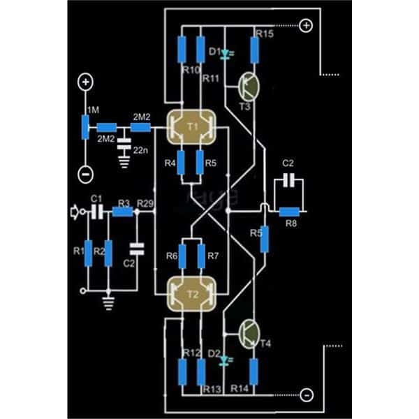
Referring to the circuit diagram, we see that the input stages primarily consists of two differential amplifiers.
The blocks T1 and T2 are actually matched paired dual transistors in one package, but you may go for discrete transistors, just make sure their hFEs are properly matched. Use a couple of BC 547 and BC 557 for the NPN and the PNP types respectively.
A differential configuration is probably the perfect way of integrating two signals, for example here the input and the feedback signals are mixed so efficiently.
Typically the ratio of the collector/emitter resistances of T1 determines the amplification of this stage.
The DC operating reference for T1 and T2 is received from a couple of transistors T3 and T4 along with the associated LEDs.
The above LED/ Transistor network also helps to provide a constant current source to the input stage as it virtually remains unaffected to ambient temperature variations, but preferably the LED/ transistor pair should be attached together by gluing them together or at least soldered very close to each other over the PCB.
Immediately after the coupling capacitor C1, the network comprising of R2, R3 and C2 forms an effective low pass filter and helps maintaining a bandwidth to a level suitable for the amplifier.
Another small network at the input, involving a 1M preset and a couple of 2M2 resistors helps adjusting the off-set voltage so that the DC component at the output of the amplifier stays at zero potential.
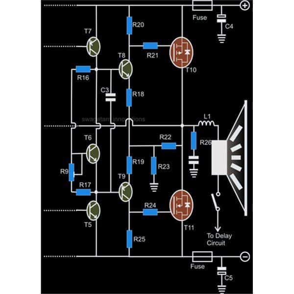
After the differential stage an intermediate driver stage is introduced comprising T5 and T7.
The configuration consisting of T6, R9 and R17 forms a kind of variable voltage regulator, which is used to set the quiescent current consumption of the circuit.
The boosted signal from the above stage goes to the driver stage consisting of T8 and T9 which are effectively used to drive the output power stage involving the HEXFETs T10 and T11 where the signals ultimately undergoes a massive current and voltage amplification.
From the diagram it is clearly identifiable that T10 is a p-channel and T11 is an n-channel FET.
This configuration allows efficient amplification of both current and voltage at this stage.
The overall amplification is though limited to 3 due to the feedback wiring of R22/R23 and also with R8/C2. The limitation ensures low distortion at the output.
Unlike bipolar transistors, here the outputs stage incorporating HEXFETs have a distinct advantage over its age old counter part.
HEXFETs being positive temperature coefficient devices are equipped with the inherent property of limiting their drain source as the case temperature tend to get too hot, safeguarding the device from thermal runaway situations and getting burnt off.
Resistor R26 and the series capacitor compensate the rising impedance of the loudspeaker at higher frequencies.
Inductor L1 is placed to safeguard the loudspeaker from instantaneous rising peak signals.
Parts List
- R1 = 100K = 1
- R2 = 100K = 1
- R3 = 2K = 1
- R4,5,6,7 = 33 E = 4
- R8 = 3K3 = 1
- R9 = 1K PRESET =1
- R10,11,12,13 = 1K2 = 4
- R14,15 =470E = 2
- R16 = 3K3 = 1
- R17 = 470E = 1
- R18,19,21,24 = 12E = 4
- R22 = 220, 5 WATT = 1
- R20,25 = 220E = 2
- R23 = 56E, 5 WATTS = 1
- R26 = 5E6, ½ WATT = 1
- C1 = 2.2uF, PPC = 1
- C2 = 1nF = 1
- C3 = 330pF = 1
- C6 = 0.1uF, mkt = 1
- T3 =BC557B = 1
- T4 = BC547B = 1
- T7,9 = TIP32 = 2
- T5,6,8 = TIP31 = 3
- T10 = IRF9540 = 1
- T11 = IRF540 = 1
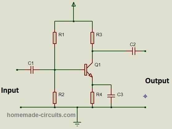
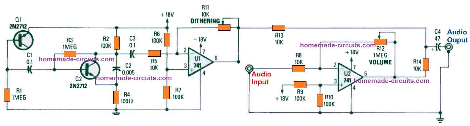
An alternate version of the above explained 250 watt power amplifier can eb seen in the following diagram having all the details regarding the components:



Questions & Answers
Dear Swagatam, how can you declare this amplifier as a 250 Watt output power???
The power supply is +/- 35 Volt, hence the voltage swing is 70 V-pp. The RMS value of 70 V-pp is 35/1.41, i.e. 25 V-RMS. As the RMS power is (V^2)R (R is the output impedance), the power will be about 80 Watt with 8 Ohm.
Thank you Piero,
You are correct with your calculations.
The post was created some 10 years ago so maybe there was some misunderstanding with the calculations during that time.
But no worries, the amplifier devices can be suitably upgraded to handle up to 120V DC and reach up to 250 watts.
Alternatively you can try doing the same with the following simple concept and get up to 300 watts power output:
https://www.homemade-circuits.com/how-to-make-simplest-100-watt-mosfet/
Thank you Swagatam for your quick reply.
I have another question about this schematics: I’ve been taken aback by the fact that the two mosfets are common source, contrary to the vast majority of other circuitries (including your proposed 100W amplifier).
I’m, however, very curious to go in detail with this project, maybe simulating it with LTspice.
If I come up with something, I’ll come back to you.
Kind regards,
Piero.
Hi Piero,
there are basically two types of MOSFET output configurations in a MOSFFET power amplifier
1) Drain-connected and 2) Source-connected.
In drain-connected topology as shown in last diagram of above article, the MOSFET drains are connected together to form the output. This topology has the advantages of high voltage gain characteristics and can be used for both voltage and current amplification.
So the drain-connected topology as shown in the last diagram above is better compared to source-connected configurations which are commonly used in other amplifiers.
If you have any further updates please let us know…
Swagatan,
Can I also use 20N60C3 mosfet and it’s complementary transistor on the output stage of the DJ thumping amplifier?
Mathews, no, this MOSFET cannot be used.
Hello there,
May I please find out the maximum voltage supply for the DJ amplifier mentioned above.
It is around +50V, -50V
Sir, I want to make a 500W dual channel class-d amplifier with sound frequency 1Hz to 100kHZ.
Please guide me.
Many thanks in advance
Hi Shamoon, sorry, 500 watt looks too high, I do not have the design at this moment!
Hi Swagatam,
I am planning to make a 200W RMS Subwoofer , can I use this CKT as it is ? what should be my LPF at the input , can you suggest , also I about the protection circuit what are the 25 VAC inputs , from where are they derived. would appreciate a reply thanks
debu.dasgupta@gmail.com
Hi Debu, you can try the last circuit from the following article for the LPF
https://www.homemade-circuits.com/make-this-low-pass-filter-circuit-for/
for the amplifier circuit, I will rather recommend the following circuit, and not the above one since it is an overkill:
DIY 100 Watt MOSFET Amplifier Circuit
one pair IRF540/9540, +-35V =250W??????????? maybe 50W
How do you calculate wattage???
See below:
+/-35 x 10 amps = 350 watts
IRF540/9540 =max. dissipation 150W
what is max dissipation, please define? and what about the VDS and Id values??
the above circuit is rated at 250 watt and can be extended upto 400 watts by increasing the supply upto 80V, but this would be possible only when the mosfets are mounted on sufficiently large heatsinks
T14 is darlington? OMG. Why?
hi sir am looking for 160 watts rms 4 ohms sub woofer amplifier single channel. can u suggest any power amp IC or mosfet based circuits .
Hi chari,
you can try the following amplifier circuit
https://www.homemade-circuits.com/how-to-make-simplest-100-watt-mosfet/
Hello sir wish you and your family a bright new year
Thanks Raghavendra, wish you too and your Family a very happy and a prosperous New Year
Thanks sir for doing all help full need
you are welcome!
what type of speaker should I use?
Any loudspeaker, rated at 4 ohms, 300 watt
Hello sir both the circuits that you have sent to me are working and thanks very much and another thing to ask you sir is which ic is better or good for audio amplifier that is la4440 or stk 4141
Hello Raghvendra,
I am glad it worked for you! both the ICs are almost similar with their specs, LA4440 is slightly lower in wats than the STK4141, Its 19 watts while the STK is 25 watts…but STK looks quite obsolete now…
Hello Sagatam Majumdar. There are inconsistencies in the values of some of the parts between the schematic at the bottom of the page and the parts list. For example, C3 and C6. They have a value on schematic and a value in part list. Witch one is the correct value?
Thank you
Hello Mihai, slight differences in the component values will have no affect on the designs…however you can preferably go with the last diagram which is the original one.
Sir, Send easy method, testing the transistor and MOSFETs
Vijay, there's only a standard method to test BJT and mosfets….BJTs are easy to test but mosfets are not….you can refer to youtube and search this, you will be able to find some video tutorials….
but you will have to remove the transistors from the PCB before checking them.
Sir,I want post PCB image, Wts is email
Vijay, sending PCB image will not help, you will have to troubleshoot it yourself, or build it again from the scratch, it's not so difficult…..keep trying you will succeed.
Sir, any one done/tested this ckt and got success
All these circuits are taken from elektor electronics magazine, and these have been tested by the elektor electronics engineers.
Please, help me sir I spend more time in this ckt but no success
build a new circuit and this time build the lat circuit from this article
https://www.homemade-circuits.com/2012/01/how-to-make-hi-fi-100-watt-amplifier.html
this circuit was tested by me personally.
i too had problems at first, and i was very new to electronics at that but i could troubleshoot it myself and make it work perfectly.
make sure your parts are of good quality.
Sir I connected ammeter in series with positive by shorting output to ground,but in multimeter no reading only zero
If the ammeter is showing nothing then how come R16 is getting hot?
check quiescent current by shorting the input terminals, and by removing the speaker….don't short the output.
Sir, R23 get heating solved by attending loose connection,but now R16 getting heated and no audio output
Vijay, that means you might have other faults also, or a transistors may be faulty or wrongly connected….I cannot troubleshoot your circuit without seeing it.
And R23 getting heat
Sir I made PCB and all parts placed but no sound only humming sound in speaker,
I connected multimeter plus to output and mins to GND, range 20v DC for feedback reading its getting 15v and no
Variable even I adjusting R9 i.e 1k port
Vijay, how did you adjust the 1K preset??
It's for setting up the quiescent current.
please read the following article to learn how to adjust the preset for setting up the correct quiescent current.
quiescent current means current which the amplifier will consume without any music, or in the idle state.
https://www.homemade-circuits.com/2012/01/how-to-make-hi-fi-100-watt-amplifier.html
Which is more output sound. 250w dj amplifiers or ic 4440 amplifier
you can yourself compare by checking their datasheets
sir, already i brought parts as per old circuit(total=800 Rs), so lets continue.which is that first R5 & C2 or after that? and (small doubt it will work)
Vijay, it is the right side R5, and C2…yes it will work
Tell the values as soon as possible sir,I will Wait.
A updated a similar diagram at the bottom, you can make it accordingly…
R5 = 22K
C2 = 330pF
Sir In this circuit,mentioned name are double, that is R5 & C2. Value are same?
No it could be a mistake, the values are not same I don't remember now, I'll have to check it in my old books, it may take little time may be two days
what is value of capacitor c4,c5 and capacitor series with R26
R26 capacitor is 0.1uF/100V
2200uF/50V
sir, i am right speaker one end is connected to ground through delay circuit!
yes that will do!
Sir, what about delay circuit? give/guide me in details
any nearby value will do!
half ckt builted on bread-board, waiting for alternative capacitor value from u sir!!
thx sir, 330PF, 22nF capacitor not available, any alternative?
Vijay, you can try the following circuit
https://www.homemade-circuits.com/2013/02/make-this-simple-delay-on-circuit.html
all parts are ready to built, but little confustion what is T1 & T2 (any other alternate transistor if not aveailabe pair transistor)
Thx sir
or alternatively you can simply use two BC547 and two BC557 for the NPN and PNP pairs respectively by matching their hFe values as close as possible.
those are "matched transistor pairs", please google "100mA NPN matched transistor pair" and "100mA PNP matched transistor pair"…..you will be able to find the values.
sir what is the name of T1 & T2 transistor,
sir in need a circuit for 3phase induction motor protection which can automatically switched off the motor when it is over heated or one phase is off or phase is reversed or ov and uv protection
Sanket,
for heat protection you could try the first concept from this article
https://www.homemade-circuits.com/2016/08/incubator-temperature-controller.html
for single phase preventor, the following design could be employed
2.bp.blogspot.com/-XzawKd-l-0U/Uh9Vk0K4s3I/AAAAAAAAALg/IszErlsABRw/w1200-h630-p-nu/single+phase+preventor+circuit.jpg
Sir, there are showing two images of circuit.
tell me how can i connect both are.
Vivek, connect the matching dotted lines of the two images with other, for example the (+) will go to the (+) line, (-) to the negative and so on
In this ckt which type of diode is used and value mention diode d1 and d2 as given in ckt?
And which type of inductance and value?
Where i connect audio in hub or audio in socket?
D1, D2 are LEDs.
wind 20 turns of any thin magnet wire over R26.
connect music input across R1
Thanks so much for the detailed explanation. But one thing I would like to know before building it; have you or anyone else actually built the circuit using the given values?
It has been tested by the "elektor electronics" engineers
Hi Sir, what happens to power sharing & output in an amplifier using transistors A1943 & C5200 because each is 100W power dissipation(power calculations of the output stage)?
And what most contributes to how powerful an amplifier can be in TRANSISTOR AMPLIFIERS?
Hi kakooza, the transistor number is not important, it's the specifications that matter, if the specs match then the transistor will work as efficiently as expected from them.
the output devices primarily decide the power level of the amplifier, but only if the power supply is optimally rated, lower supply specs will result in poor output quality and distortions.
Dear Sir,
the voltage and amps required for this ckt?
Regards
please see the previous comment
Dear sir ,
How to make offset zero. Wat is the supply voltage…
Thanks n regards
Dear style, you can do it by adjusting R9, supply is 30-0-30V DC 5 amps
in my area(erode,tamilnadu,india) the IRF540 is 40/- rupees and IRF9540 is 50/- rupees only.
I have 4 ohm super speakers.. will you help to make a amplifier at home for suitable for this 4 ohm speakers with simple way to understand circuits and gave a proper list to used equipments in this…………… please help me…
You can try the following circuit, this is much easier, but you will need a PCB for this:
https://www.homemade-circuits.com/2012/04/how-to-make-simplest-100-watt-mosfet.html
Thanks!! Well got to get started…
I have two 6 ohm speakers and want to build a speaker system with very good quality right from scratch( from 3.5 mm jack). Got any circuit for that?
you can try this one:
https://www.homemade-circuits.com/2012/04/how-to-make-simplest-100-watt-mosfet.html
not sure about the present rates.
if i will add 2 pair of more output mosfet then how much watt i will get
You can do it, the power would increase substantially, just make sure to add a 0.22 ohm 1 watt resistors in series with the source of each mosfet, and also use separate gate resistors for each mosfets.
what about the current & voltage & ohm's rate of this amp (what is the cost of IRF9540,IRF540
you will have to find it yourself.
It's a standard design having a differential stage, followed by a driver stage and finally a power output stage.
The transformer will need to be made-to-order, the high voltage is necessary for implementing the extreme high wattage output from the circuit, and for keeping the wires and the transformer dimensions smaller.
Thanks for the link sir.
Could you please explain the circuit diagram? Also i doubt if i can find suitable transformer for the power supply section in my country. I have been searching with no result yet. can you suggest the way out?
Thanks
it's 20 turns of 22swg enameled copper wire over a 1 ohm 5 watt resistor connected parallel to it.