The proposed 40 watt electronic ballast is designed to illuminate any 40 watt fluorescent tube, with high efficiency, and optimal brightness.
The PCB layout of the proposed electronic fluorescent ballast is also provided along with the torroid and the buffer choke winding details.
Introduction
Even the promising and the most talked about LED technology is perhaps unable to produce lights equal to the modern electronic fluorescent ballasts lights.
The circuit of one such electronic tube light is discussed here, with efficiency better than LED lights.
Just a decade ago electronic ballasts were relatively new and due to frequent failures and high costs were not generally preferred by everyone.
But with passing time the device went through some serious improvements and the results were encouraging as they started becoming more reliable and long lasting.
The modern electronic ballasts are more efficient and fail proof.
Difference between Electrical Ballast and Electronic Ballast
So what’s the exact advantage of using electronic fluorescent ballast compared to the age old electrical ballast?
To understand the differences correctly it is important to know how ordinary electrical ballasts work.
Electrical ballast is nothing but a simple high current, mains voltage inductor made by winding number of turns of copper wire over laminated iron core.
Basically, as we all know a fluorescent tube requires a high initial current thrust to ignite and make the electrons flow connect in between its end filaments.
Once this conduction is connected the current consumption to sustain this conduction and the illumination becomes minimal.
Electrical ballasts are used just to “kick” this initial current and then control the supply of the current by offering increased impedance once the ignition is completed.
Use of a Starter in Electrical Ballasts
A starter makes it sure that the initial “kicks” are applied through intermittent contacts, during which the copper winding’s stored energy is used to produce the required high currents.
The starter stops functioning once the tube gets ignited and now since the ballast is routed via the tube, starts getting a continuous flow of AC through it and due to its natural attributes offers high impedance, controlling the current and helping sustain optimal glow.
However, due to variation in voltages and lack of an ideal calculation, electrical ballasts can become quite inefficient, dissipating and wasting a lot of energy through heat.
If you actually measure you will find that a 40 watt electrical choke fixture may consume as high as 70 watts of power, almost double the required amount. Also, the initial flickers involved cannot be appreciated.
Electronic Ballasts are More Efficient
Electronic ballasts on the other hand are just the opposite as far as efficiency is concerned. The one which I built consumed just 0.13 Amps of current @ 230volts and produced light intensity that looked much brighter than normal.
The have been using this circuit since last 3 years without no problems whatsoever (though I had to replace the tube once as it blackened at the ends and started producing lesser light.)
The current reading itself proves how efficient the circuit is, the power consumption being just around 30 watts and an output light equivalent to 50 watts.
How the Electronic Ballast Circuit Works
Its working principle of the proposed electronic flourescent ballast is rather straightforward. The AC signal is first rectified and filtered using a bridge/capacitor configuration.
The next comprises a simple two transistor cross-coupled oscillator stage. The rectified DC is applied to this stage which immediately starts oscillating at the required high frequency.
The oscillations are typically square wave which is appropriately buffered via an inductor before it is finally used to ignite and illuminate the connected tube.
The diagram shows a 110 V version which can be easily modified into 230 volt model through simple alterations.
The following illustrations clearly explains how to build a homemade electronic 40 watt electronic fluorescent ballast circuit at home using ordinary parts.
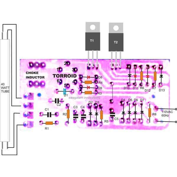
PCB Component Layout
WARNING: PLEASE INCLUDE A MOV AND A THERMISTER AT THE SUPPLY INPUT, OTHERWISE THE CIRCUIT WILL BECOME UNPREDICTABLE AND MIGHT BLOW-OFF AT ANY MOMENT.
ALSO, MOUNT THE TRANSISTORS OVER SEPARATE, 4*1 INCH HEATSINKS, FOR BETTER EFFICIENCY AND LONGER LIFE.
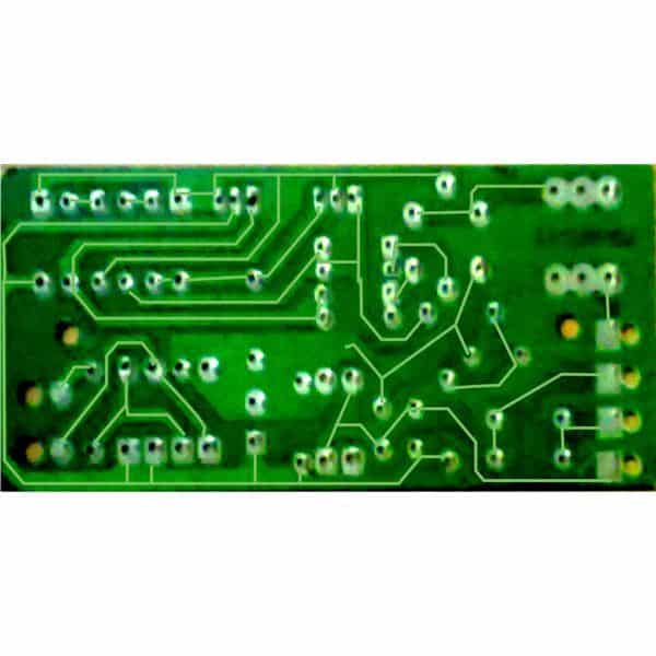
PCB Track Layout
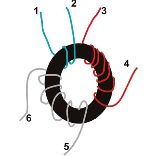
Torroid Inductor
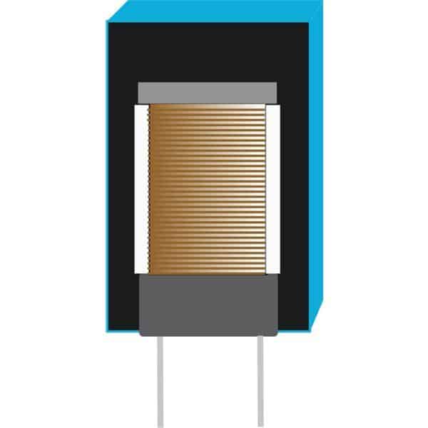
Choke Inductor
Parts List
- R1,R2,R5 = 330K MFR 1%
- R3,R4,R6,R7=47 Ohm, CFR 5%
- R8=2.2 Ohms, 2watts
- C1,C2=0.0047/400V PPC for 220V, 0.047uF/400V for 110V AC input
- C3,C4=0.033/400V PPC
- C5=4.7uF/400V Electrolytic
- D1=Diac DB3
- D2……D7=1N4007
- D10,D13=B159
- D8,D9,D11,D12=1N4148
- T1,T2=13005 Motorola
- Heatsink is required for T1 and T2.
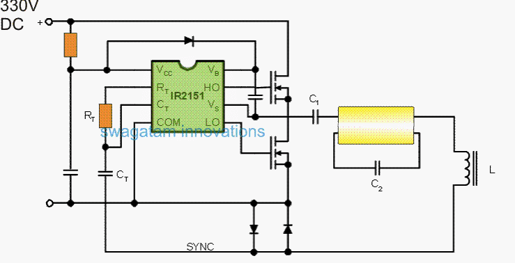
Electronic Ballast Circuit for Twin 40 Watt Fluorescent Tubes
The next concept below explains how to build a simple yet extremely reliable electronic ballast circuit for driving or operating two 40 watt fluorescent tubes, with an active power correction.
Courtesy: https://www.irf.com/technical-info/appnotes/an-995a.pdf
Main Electrical Features of the IC
International Rectifier Control ICs are monolithic power integrated circuits suitable for operating low-side and high-side MOSFETs or lGBTs through logic level, referenced to ground input leads.
They feature balanced out voltage functionality as much as 600 VDC and, contrary to ordinary driver transformers, can bring super-clean wave-forms with virtually any duty-cycle from 0 to 99%.
The IR215X sequence is actually a recently available accessory to the Control IC family and, besides the previously mentioned characteristics, the product employ a top end comparable in performance to the LM 555 timer IC.
These types of driver chips give you the developer with self oscillatory or coordinated vacillation capabilities purely with the help of alternative RT and CT components See figure below
Parts List
- Ct/Rt = same as given in the below given diagrams
- lower diodes = BA159
- Mosfets: as recommended in below diagrams
- C1 = 1uF/400V PPC
- C2 = 0.01uF/630V PPC
- L1 = As recommended in below diagram, may need some experimentation
They likewise have in-built circuitry which offers a moderate 1.2 microsecond dead-time between outputs and switching high side and low side components for driving half-bridge power devices.
Calculating The Oscillator Frequency
Whenever included in the self oscillatory form the frequency of oscillation is calculated simply by:
f = 1/1.4 x (Rt + 75ohm) x Ct
The three accessible self-oscillating devices are IR2151, IR2152 and IR2155. IR2I55 seems to have more substantial output buffers that will turn a 1000 pF capacitive load with tr = 80 ns and tf = 40 ns.
It includes minuscule power start-up and 150 ohm RT supply. IR2151 possesses tr and tf of 100 ns and 50 ns and performs much like IR2l55.
IR2152 will be indistinguishable to IR2151 although with phase cambio from Rt to Lo. IR2l5l and 2152 include 75 ohm Rt source (Equation l.)
These types of ballast drivers usually are meant to be furnished with the rectified AC input voltage and consequently these are intended for minimal quiescent-current and still have a l5V in-built shunt regulator to ensure that just one limiting resistor works extremely well through the DC rectified bus voltage.
Configuring the Zero Crossing network
Looking yet again to Figure 2, be aware the synchronizing potential of the driver. Both back-to-back diodes in line together with the lamp circuit are efficiently configured as a zero crossing detector for the lamp current. Ahead of the lamp strike, the resonant circuit involves L, C1 and C2 all in a string.
C1 is a DC blocking capacitor having a low reactance, in order that the resonant circuit is successfully L and C2. The voltage around C2 is amplified by way of the Q factor of L and C2 at resonance and hits the lamp.
How the Resonant Frequency is Determined
As soon as the lamp strikes, C, is appropriately short circuited by the lamp potential drop, and the frequency of the resonant circuit at this point is determined by L and Cl.
This leads to a change to some lower resonant frequency in the course of standard operations, just as before coordinated through sensing the zero-crossing of the AC current and taking advantage of the resulting voltage to regulate the driver oscillator.
Along with the driver quiescent current, you will find a couple of additional elements on DC supply current which are a functionality of the very application circuit:
Evaluating Current and Charge Discharge Parameters
l) Current as a result of charging the input capacitance of the power FETs
2) current resulting from charging and discharging the junction isolation capacitance of the International Rectifier gate driver devices. Each components of current arc charge-relatcd and for that reason stick to the rules:
- Q = CV
It could conveniently be observed, consequently, that to be able to charge and discharge the power device input capacitances, the expected charge can be a product of the gate drive voltage and the true input capacitances and also the input power recommended will be specifically proportionate to the product of charge and frequency and voltage squared:
- Power = QV^2 x F / f
The above mentioned associations propose the below factors when making a real ballast circuit:
1) pick the smallest working frequency according to decreasing inductor dimension;
2) opt for the most compact die volume for the power devices dependable with reduced conduction deficits (that minimizes the charge specifications);
3) DC bus voltage is normally selected, however , if there exists a alternative, make use of the minimum voltage.
NOTE: Charge is simply not a functionality of switching rate. The charge transmitted is the very same with regard to I0 ns or 10 microsecond transition times.
We will at this point take into account a few useful ballast circuits which can be achievable using the self-oscillating drivers. Probably the most well-liked fluorescent light fixture may be the so called ‘Double 40’ type which often employs a couple of typical Tl2 or TS lamps within a common reflectante.
A pair of recommended ballast circuits are demonstrated in the following figures. The first is the minimal power factor circuit, along with the other works with a novel diode/capacitor settings to accomplish a power factor > 0.95. The lower power factor circuit proven in figure 3 welcomes 115 VAC or 230 VAC 50/60/400 Hz inputs to generate a moderate DC bus of 320 VDC.
Twin 40 Watt Ballast Circuit Diagram
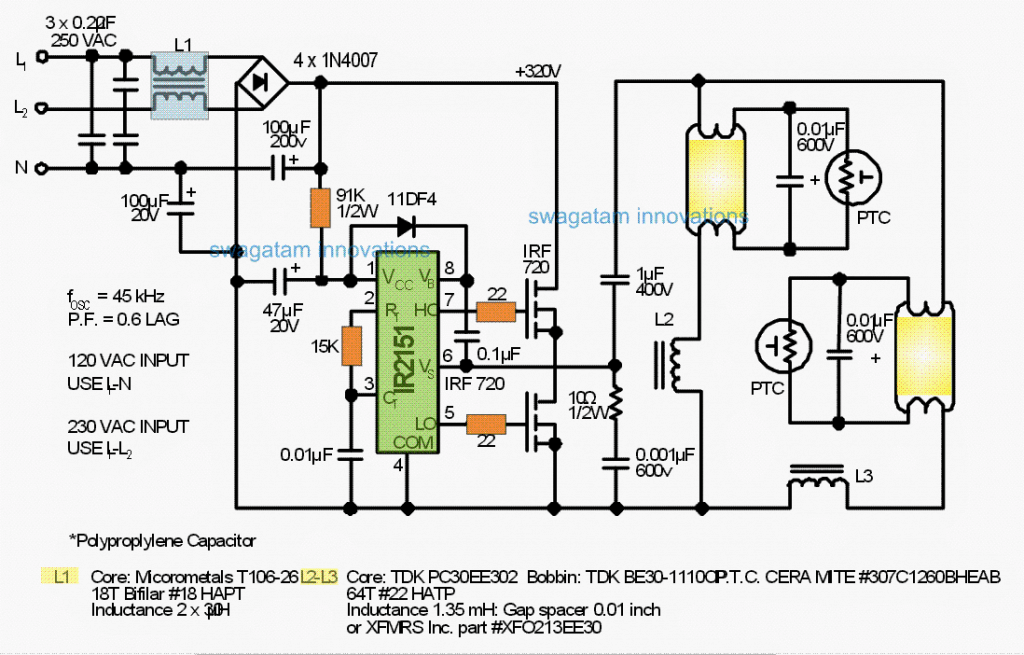
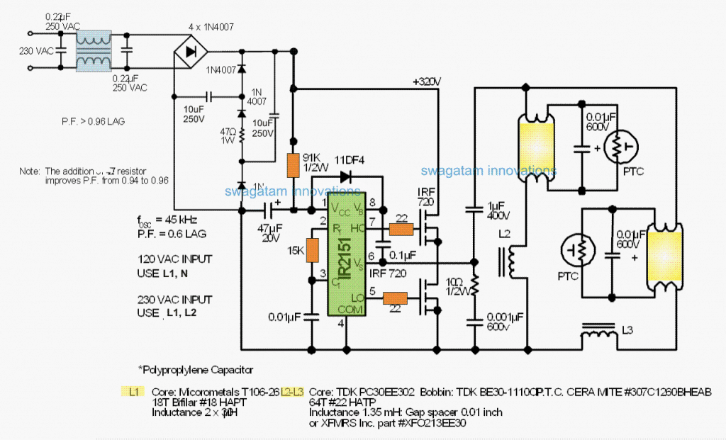
Considering that the input rectifiers carry out just close to the peaks of the AC input voltage, the input power factor is around 0.6 lagging with a non-sinusoidal current wave-form.
Such type of rectifier is simply not advised for anything at all apart from an assessment circuit or reduced power compact fluorescent and without a doubt could become unwanted as harmonic currents in power supply devices are additionally lessened by power quality restrictions.
The IC uses a Limiting Resistor only to Operate
Observe that the International Rectifier IR2151 Control IC performs directly off thc DC bus by way of a limiting resistor and pivots at close to 45 kHz in conformity with the given relationship:
- f = 1/1.4 x (Rt + 75ohm) x Ct
Power for the high side switch gate drive arises from a bootstrap capacitor of 0.1 pF and that is charged to roughly 14V anytime V5 (lead 6) is dragged low within the low side power switch conduction.
The bootstrap diode l IDF4 prevents the DC bus voltage as soon as the high side change conducts.
A fast recovery diode ( <100 ns) is necessary to be certain that the bootstrap capacitor will not be moderately discharged since the diode comes back and obstructs the high voltage bus.
The high frequency output in the half-bridge is actually a square wave with extremely fast changeover periods (around 50 ns).
To avoid abnormal extended noises through the fast wave fronts, a 0.5W snubber of 10 ohm and 0.001 pF is employed to minimize the switch periods to just about 0.5 ps.
Featuring a Built-in Dead Time Facility
Observe that we have a built-in dead time of 1.2 ps in the IR2151 driver to stop shoot-through currents in the half-bridge.
The 40 watt fluorescent lamps are controlled in parallel, each using its own L-C resonant circuit.
Approximately four tube circuits could be operated from a single set of two MOSFETs measured to match the power level.
The reactance valuations for the lamp circuit are picked from L-C reactance tables or through the formula for series resonance:
- f = 1/2pi x square-root of LC
The Q of the lamp circuits is pretty small simply because of the advantages of functioning from a fixed rate of recurrence which usually, obviously, may differ due to RT and CT tolerances.
Fluorescent lights tend not to generally need extremely high striking voltages therefore a Q of 2 or 3 is enough. ‘Flat Q` curves often originate from bigger inductors and small capacitor ratios in which:
Q = 2pi x fL / R, wherein R is often greater because a lot more turns are employed.
Soft-starting during tube filament pre-heating may be inexpensively contained by utilizing PTC. thermistors around each lamp.
In this manner, the voltage along the lamp steadily boosts as the RTC. self-heats right up until eventually the striking voltage together with hot filaments is achieved and the lamp illuminates.


Comments
sorry for your disturbance ,sir i have one more problem regarding my project . my trolley run in a straight path so sir what can i do so that it can change its path automatically
how do you prefer it to take the turns? depending on what?
sir, i have made a robot that implement swatch bharat abhiyan . in project i have a problem that is "what source of energy i should use 1)solar energy but it cannot run 3 dc motors and 1 c.p.u fan 2)batteries but the weight will create problem 3)a.c. current but the plug point and the wires will create problem .so sir please kindly advice me .
thank you for your kind advice
use batteries, sealed SMF type 12V 25AH,, and build the trolley as suggested in the previous comment.
hello sir , i have one more problem regarding to my project swatch bharat abhiyan robot that described before , sir i thought that i will use solar pannel as a source of energy but how to run three dc motor and a c.p.u fan using a solar pannel . if i use batteries then the heavy weight will create problem .if i use ac current then the wire and the plug point will create problem .sir please advice me what to do .
hello Ritish,
batteries will not create any problems, your trolley will easily run on the road with the CPU fan operating along with the batteries…..
use good quality motors for the wheels.
for more info you can read the following article:
https://www.homemade-circuits.com/2015/04/remote-controlled-trolley-circuit.html
Sir ..i require 11-18 watts electric ballast..can i proceed this same procedure
thank you sir
You can try the following circuit instead:
https://www.homemade-circuits.com/2014/04/single-chip-electronic-ballast-circuit.html
sir i think for taking off light weight objects like paper or leaves a hi speed C.P.U fan is sufficient with a net in front of it to stop collision between paper and fan.
thank you sir for your kind advice
ok sir i will try
It should work, a practical test will confirm it….
hi sir i want to make a robot that can implement the Swach Bharat Abhiyan for school science exhibition .
for this i had planned to make three robo cars – first will work like a vaccum cleaner which took light weight things like paper and leaves to clean ,second will clean the splits on road or anywhere ,third will took off heavy things .but sir i have one problem with third robot.if anything comes in front of it ,it will took off that object but suppose there is a valuable object like a money purse than it will also took it .sir what can i do so that my robot took off only the waste things not any valuable things.
thank you sir for your advice
Hi Ritish,
that's not feasible, you cannot make a vacuum cleaner understand the difference between a valuable material from a scrap material….but this can be handled by a human being at the other end who could segregate the materials appropriately…,…but I don't think you will get too many valuable things on road…. 99% will be scrap and garbage.
can i do it on pcb ie pro-ject board GLno.12 i am a wireman and most of my client call me to replace electronic ballast tube light. but by reading you 40watt electronic ballast i feel i should try to repair all broken ballast it will hwlp my clent in some way. other they have to bring new one from the market.
I won't recommend the above circuit since the technology is quite old and not very reliable, today there are IC based much improved circuits which are very reliable and long lasting, you could try one of those circuits…here's one article that may help you regarding the subject:
http://www.irf.com/technical-info/appnotes/an-995a.pdf
To all the people asking for values and such, you should try LTSpice or another analog electronics simulator. It even has power analysis if you're trying to figure out how much wattage is going to be dissipated by the transistors, for example. Sadly, it does require some knowledge of how to make a schematic and figure out their 'unique' interface. Luckily, tons of good tutorials with pictures, though!
I haven't seen if they simulate a fluorescent bulb, but you can add devices with custom behaviors/curves. Even without that, these programs are wonderful for learning electronics and well worth the effort to learn!
please publish a circuit of electronics starter for 40 watt fluorescent tube light with magnetic ballast.
OK I'll try to design and publish it soon….do keep in touch
Bro, everything is shown quite clearly in the article above, if you are having difficulty understanding, you can specify those… I'll clarify them immediately.
If possible I'll try to produce a clearer PCB diagram.
Hi…bro…
if you can send me any clear pic of PCB diagram or layout diagram….i can post the clear schematic diagram for you & everyone else..this will also helps me too…
waiting for your esteemed reply….
TIA
Hi…
i did everything as you stated. only thing am stuck with is..with the choke & torroid coil. can you please specify much more details or mention some equivalent parts avail in the market.
TIA
finally i able to make 40w cfl design using mosfets,they are more efficient and more reliable than transistor.i made 3 of them and they are working great.
mosfets circuits are always better
sir,
which date you posted the comment pl tell me.Tell me the specification of coil inductor,terriod and Mov.
suresh, see the comment replies from Akarsh above
Hi,
Can you please explain how the alterations can be done to use directly in 230 V 50hz Supply.With Corrected printed pcb.Please help me.
Thanks in advance.
Hi, the circuit is designed for 220v AC, and the PCB is also correct except one small error which I have explained in one of the above comments
well not in this circuit but how to connect mosfet with this type of circuit? i mean how to provide gate voltage with zener when supply is 240v dc
here's one example you may refer to:
4.bp.blogspot.com/-q2OdIb3tOWQ/UvcbVFrEzKI/AAAAAAAAGRo/ROKukGqYUx4/s1600/surge+suppressed+led+driver+circuit.png
please provide me some idea to use irf840 in place of 13005 in this circuit
mosfet will not work properly in place of a BJT in a ballast circuit…because the components are specifically selected for a BJT operation and not for a mosfet.
Hi,
For Electronics Ballast,how we can decide the number of turns for E type inductor an torroid.And how we can calculate it.
I have no idea about it, it will depend on the given manufactures specifications.
how to manufacture a electronic choke
you will need to invest minimum 10 lacs initially and wait for 6 months for the first payment to arrive without stopping the production.
you can try the following circuit, it will work with ftls also:
https://www.homemade-circuits.com/2014/04/single-chip-electronic-ballast-circuit.html
Can u guide me to manufacture a ftl electronic choke
i want to manufacture choke can u guide me
in that pcb track layout, where is the line that does not touch a point touches…?
thank you
it's linked to the central large copper containing 6 pads
sir, can u please correct the track layout and post….
please please…
sir,
i dont get you..
i asked you that, there is a track which does not touches any pad.I asked you to which pad that track should be linked.?
thank you
at the bottom center edge of the PCB, you will find three pads closely placed.
the rightmost pad needs to be linked with the track passing just below it.
Bro make i clear it first.U said i have to take only 2 cables from each pairs of cable from out put section of the ballast.then i have to connect that 2 cables individually with any one pin on either side of the tube.is This configuration is allowed for 2 end fused tube or 1 end fused tube?if possible pls make it clear with diagram.
yes this wiring method will work for fused tubes.
bro today im again try to reuse fuse tube lite also CFL as per ur instruction(shorting lite ends) but when i give power then lite start blinking with some time then it run.Is this normal condition or i continue this way will my ballast or CFL burst?
bro connecting or shorting the two pins of the tube is not required.
simply take out single wires from the corresponding sides of the ballast and connect them to any one pin on either side of the tube
Bro how long i can reuse the fused tube light in this way(shorting fused end) safely without bursting my electronic ballast?
bro, shorting the tube ends will never affect a good quality ballast in anyway, so you can expect a normal operation from it even with the ends shorted
Bro how can i drive 40w fused(1 end/ 2 end)Tube light by electronic ballast like as electrical ballast? Although i have tried it by shorting the fused end of the light but it do blink when power on then it run.Sometime in the mid of running of light it start blinking then get stable.In this way i reuse that fused light some day but my ballast burst out.So what is the safe solution of it?
Bro, the one that is shown in the above article can be used for the same purpose, I have already tried it and it worked for me
Sir can you please explain the full circuit working and please give the circuit diagram
Hi. I want this to run only from 12 or 24volts dc. Can you help please I want to power a 42 or 57 watt cfl lamp. Osram dulux te plus
sir please send choke circuit for the 40W tublight and also clear pcb layout.
thank you
PLEASE GIVE CLEAR CIRCUIT DIAGRAM
Initially please connect a 60 watt bulb in series to confirm the results first…. if the tube illuminates would confirm your circuit and then we can proceed with further improvements like adding thermister, MOV etc.
please also note that D2 cathode is connected to the track which is passing just under it
hai myself githin
Iam interested to know details about ur design, i got the concept but i want to know the design parameters.
could u please tell me.
1) which freg the oscillator works
2) need of chock and the value
3) need of Torrid Inductor
4) how can i calculating the watts
( u discussed earlier changing the capacitor value need calculation method)
i hope u will guide me my mail address vgithin@gmail.com contact no 09345772248.
need ur contact details
Hi Githin,
I copied this from a ready made sample, so I don't know much about the calculations.
The choke can be any type of coil wound over any type of ferrite core…use maximum possible number of turns, example you can try with 200 turns of 30 swg wire.
I have explained the torroid detail in the article.
Please snd me circuit daig….