• Skip to main content
  • Skip to primary sidebar

Homemade Circuit Projects

Need circuit help? Post them in the comments! I've answered over 50,000!

Blog | Categories | About | Hire Me | Contact | Calculators-online
You are here: Home / LM317, LM338, LM396 Calculator

LM317, LM338, LM396 Calculator

LM317 Resistor Calculator

R1 Resistor (Ω)

R2 Resistor (Ω)

Output Voltage (V)


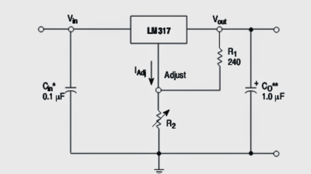
This LM317, LM338 calculator software is used as a tool to determine the value of the voltage adjusting resistor needed to assign the output of an LM317 to an allocated degree. Normally R1 is 220 ohms or 240 ohms, however it could very well be a different value for instance 150 or 470 ohms. Go with a value for R2 and click the "Calculate" button. The LM317 output value is displayed in volts.

Take into account that the input voltage to the LM317 is required to be a minimum of 1.5v higher than the output voltage. To increase current you can configure an outboard transistor across the input and output pins of the IC

Reader Interactions

Questions & Answers

Total Posts: 11
Newest Oldest
Justo Ancajima Yarleque
September 11, 2022 • 4 years ago #133099

Muy buena información me gustaría seguir recibiendo

Reply
SwagatamAdmin
September 11, 2022 • 4 years ago #133107

Thank you!

Reply
ananda
July 19, 2022 • 4 years ago #131716

I want to make the current limited PWM Li-Ion charger to charge 15V,/ 6800 mah Li-Ion battery.

Reply
SwagatamAdmin
July 20, 2022 • 4 years ago #131728

Sorry, I do not have a PWM based charger with me at this moment.

Reply
alfredo schulz
July 16, 2022 • 4 years ago #131601

sus terminos son exactos,es uno de mis maestros preferidos desde ahora. GRACIAS MAESTRO.

Reply
SwagatamAdmin
July 16, 2022 • 4 years ago #131606

My pleasure Alfredo!

Reply
Owen
February 28, 2022 • 4 years ago #114416

Just want you to include feedback on the arduino inverter, thank your the best.

Reply
Joakko
June 23, 2020 • 6 years ago #79775

Hi. very, very gooood page.Please write me to send you some circuits and to clear daubs. Thanks so much Joakko

Reply
Olamide Emmanuel
February 22, 2020 • 6 years ago #76851

Observing the above software I discovered that the parameters are related by V=(1.37XR)/r. Where V is the outputvoltage, R is R2 and r is r1.
Please try this with many values of resistors it should swing within this constant.
Swag. kindly look into my last mail on using micro-controllers to design inverter with just a single transformer.
Cheers.

Reply
SwagatamAdmin
February 22, 2020 • 6 years ago #76856

OK you mean the reference voltage value is 1.37 V instead of the specified 1.25 V in the datasheet…I have not yet investigated I may do it in my free time…

Reply
Kannan
November 6, 2019 • 7 years ago #71825

Very good explained thanks

Reply

Need Help? Please Leave a Comment! We value your input—Kindly keep it relevant to the above topic! Cancel reply

Your email address will not be published. Required fields are marked *

Primary Sidebar


Categories

  • Arduino Projects (95)
  • Audio and Amplifier Projects (134)
  • Automation Projects (18)
  • Automobile Electronics (103)
  • Battery Charger Circuits (89)
  • Datasheets and Components (109)
  • Electronics Theory (150)
  • Energy from Magnets and Earth (40)
  • Games and Sports Projects (11)
  • Grid and 3-Phase (20)
  • Health related Projects (27)
  • Home Electrical Circuits (13)
  • Indicator Circuits (16)
  • Inverter Circuits (100)
  • Lamps and Lights (163)
  • Meters and Testers (72)
  • Mini Projects (28)
  • Motor Controller (68)
  • Oscillator Circuits (30)
  • Pets and Pests (15)
  • Power Supply Circuits (91)
  • Remote Control Circuits (50)
  • Security and Alarm (65)
  • Sensors and Detectors (107)
  • SMPS and Converters (46)
  • Solar Controller Circuits (62)
  • Temperature Controllers (44)
  • Timer and Delay Relay (50)
  • Voltage Control and Protection (44)
  • Water Controller (37)
  • Wireless Circuits (31)


Circuit Simulator

circuit simulator image


Subscribe to get New Circuits in your Email


Other Links

  • Privacy Policy
  • Cookie Policy
  • Disclaimer
  • Copyright
  • Videos
  • Sitemap

People also Search

555 Circuits | 741 Circuits | LM324 Circuits | LM338 Circuits | 4017 Circuits | Ultrasonic Projects | SMPS Projects | Christmas Projects | MOSFETs | Radio Circuits | Laser Circuits | PIR Projects |


Recent Comments

  • Swagatam on 2 Cool 50 Watt Inverter Circuits for Students and Hobbyists
  • way on 2 Cool 50 Watt Inverter Circuits for Students and Hobbyists
  • Swagatam on 2 Cool 50 Watt Inverter Circuits for Students and Hobbyists
  • Swagatam on The Perfect FM Radio Circuit using TDA7000 IC
  • Swagatam on 9 Simple Sine Wave Generator Circuits Explored

Social Profiles

  • Twitter
  • YouTube
  • Instagram
  • Pinterest
  • My Facebook-Page
  • Stack Exchange
  • Linkedin

© 2026 · Swagatam Innovations