This circuit can be used like a tree ornament, however the LED star circuit explained here has a variation; it's completely electronic and it provides the impression of an exploding and imploding 6 arm star.
A block diagram of the circuit can be seen in the Fig. 1 below, configured using 3 components: oscillator, counter, and display.
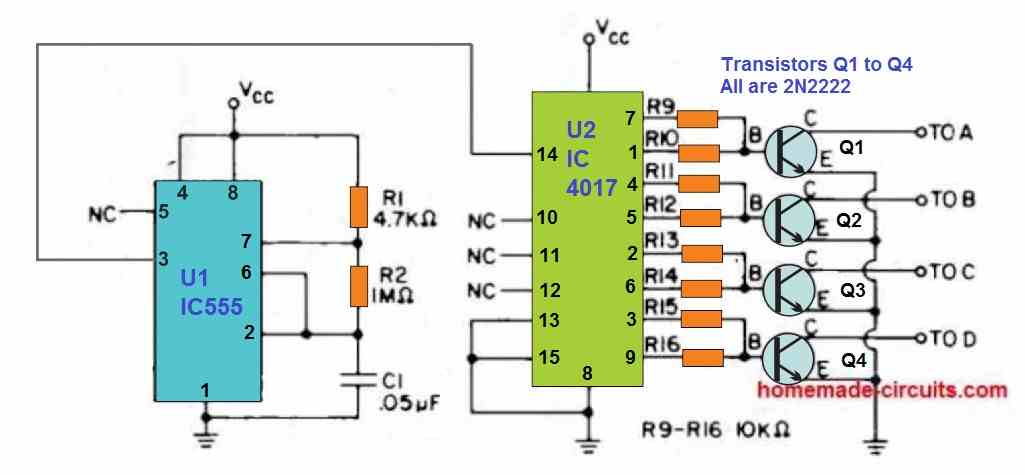
The oscillator stage is built around a LM 555 integrated circuit setup like a multivibrator.
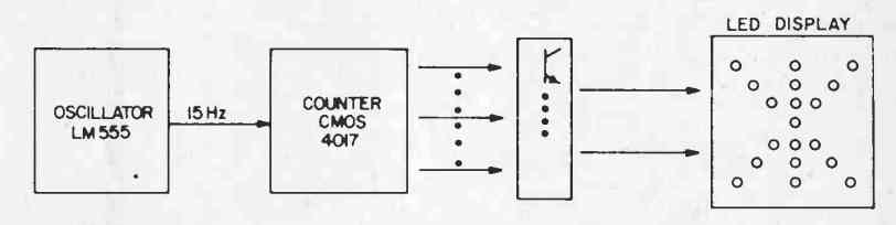
The pulses generated by this oscillator are delivered to a decade up-counter chip using the IC 4017, which has its ten output lines turning high sequentially.
These output channels are sent across four encoding and driving transistors which light up the connected LEDs in the specified pattern.
In this LED star circuit, the values of resistors R1, R2, along with C1 could be modified in case you want the Star to light up at some other rate.
Transistors Q1 -Q4 could be any general purpose NPN BJT rated at a 50mA collector capacity. The complete assembly should not take over two hours.
Overall expense of the design should cost less than $5 and could be possibly reduced for those who have a couple of components from their electronic junk box.
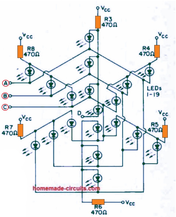
Design of the LED star is not really crucial apart from the placements of the LEDs. Different modifications from the proposed design might or might not be aesthetically attractive.
If the LED positioning is not done correctly might stop some of the LEDs to light up. The power supply for the simple LED star circuit can vary from 5 -12 VDC with 6 to 9 V being the most suitable.
A 9 V PP3 cell will allow the circuit to operate for approximately five to six hours, however bigger lead acid batteries should enable the circuit to function for a considerably longer time period, due to the fact that the current consumption of the project is 40 mA at 6 volts.
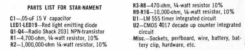
Parts List
Using Multicolor Flashing LEDs
The 20nos of RGB LEDs shown in the circuit are transparent and characterized by a diameter of 5mm. When supplied with a continuous voltage of 3.5V, it begins an amazing cycle of colored effects with an automatic changing rhythm.
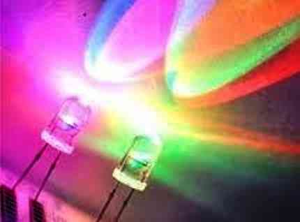
Its color changes from blue to red, then to green, with emission duration that are infinitely variable.
In addition, the transitions from one color to another are smooth, that is, they are linked.
As for the three fundamental colors, all shades of the visible spectrum are formed.
Figure 1 shows the result of mixing these fundamental colors two by two.
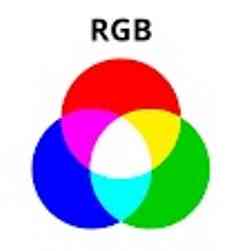
The wavelengths of the displayed colors are:
- For red: 625 nm
- For green: 520 nm
- For blue: 470 nm The nanometer (nm) is one billionth of a meter.
For an average consumption of 20 mA, the perceivable luminous intensity is:
- 1600 mcd for red
- 2800 mcd for green
- 1300 mcd for blue The millicandela (mcd) is one-thousandth of a candela, the base unit of luminous intensity perceived by the human eye.
Making a Star Using Multicolor LEDs
The proposed circuit Figure 2 below shows the simplest possible circuit.
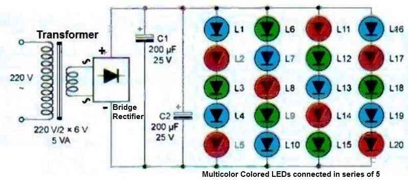
A transformer lowers the mains voltage to 12V, while a bridge rectifier rectifies the two alternations.
This power supply is completed by the parallel connection of two 200 uF capacitors to achieve the necessary smoothing.
As the star has twenty LEDs, they have been grouped to form four parallel branches of five LEDs each.
This results in a quasi-continuous voltage whose value is close to 18V.
As a result, a voltage of approximately 3.5V is obtained at the terminals of each LED, which operates under optimal conditions.
Figures 3 below shows the PCB layout for the he "star" module
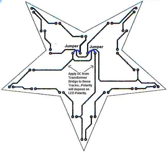
Pay attention to the orientation of the diode bridge, electrolytic capacitors, and LEDs. The two modules are connected to each other by two wires.
Once powered, the LEDs begin their amazing dance. At first, the luminous and colored effects are in phase.
But quickly, after a few minutes, a complete desynchronization occurs between them. The resulting effect is even more aesthetic. The impression of twinkling, supported by the high luminous intensity of the LEDs, is truly spectacular.
Usage recommendations
For safety reasons, we recommend enclosing the power module in a plastic box that will be placed near a power outlet. From this box, two wires will carry the low voltage needed for the LEDs to operate.
Therefore, our star can be positioned at the top of a Christmas tree, and the "two-conductor" cable can be hidden in the foliage to avoid spoiling the overall aesthetic.
It is important to note that the LEDs produce a strong light, so it is preferable not to look directly at them to avoid any risk of temporary blindness.
Finally, this star can be used in many other situations, such as a table decoration for a wedding, birthday or themed party. In any case, it will add a touch of magic and enchantment to your interior.
I was thrown off by the term “multicolor LEDs.” I was trying to interpret the diagram as using RGB LEDs, which these are not. You are just using LEDs of different colors. My bad. Thanks.
These multicolored LEDs automatically flash, producing alternate RGB patterns continuously as long as they are powdered
Hello, I hope you are well.
My friend and I are hoping to construct your star ornament but we have run into some problems. We’re confused by the diagram you included with the transformer and the LEDs connected in series of 5. In this diagram, there are 20 LEDs, but in the previous diagrams and instruction list, there are only 19 LEDs. How does the diagram with the transformer fit into this design? Thank you!
Hello Brigitta,
The second design with 20 LEDs is not related to the first circuit design. Both are two different designs.
Let me know if you have any further doubts.
Thank you so much! I understand it better now. I have constructed a working prototype and now plan to actually make the PCB. I am working in KiCad. It is my first time and I am struggling to make a design without crossing connections. My design is different from yours, but apart from the positioning of LEDs, it is the same as your first circuit design. Could I possibly see your PCB design if you did it in KiCad or a similar software?
Sounds great! Glad you could make a working prototype of the first circuit. However, I have not yet created a PCB design. I used to make PCB designs on CorelDraw, but in my new laptop I do not have a CorelDraw software, I may consider installing it soon in my laptop.
i made it that it works so nice.
Hello Swagatam,
I hope you are fine. I often visit your projects which are very simple to make and very informative. I am into electronics basically in automated and manual machines. I was used to repair and run them. Now I am retired and fulfilling my niche by making electronic project at home. Recently I have made some RGB led cubes successfully and now at present I am working on 4x4x4 RGB led cube using TLC 5940NT ics. I am having some problems to make it run properly. I am not able to run all leds according to Arduino program. And I am not at all good at programming.
Please let me know if you can help with this. I can upload schematic and my pcb pics for your reference.
Many thanks in advance.
Thank you Purushottam, Glad you liked my posts! Actually my Arduino knowledge is also not good, so it can be difficult for me to solve your query. Apart from Arduino if you have any problems with a digital or analogue based circuit, I can definitely help!