In this post I have explained how to design and build a chasing LED light wave effect generator circuit, using IC 4017. Basically, the circuit is an enhanced form of LED chaser circuit which generates a wave like simulation on the LEDs as they cycle and pulse from high brightness to low brightness sequentially.
This circuit idea was requested by Mr. Dillard.
Circuit Specifications and Objective
This is intended for a 12V DC system with nine small LED lights resembling side marker lights (unspecified amperage draw). I require a user-friendly controller that allows easy programming for simple delay/time adjustments (considering I lack programming skills). Additionally, it should be weather-sealed and compact for convenient mounting.
The LED lights are to be arranged horizontally from left to right (positions 1-9). The controller's functionality is outlined as follows:
- All lights start at maximum brightness, initiating the cycle. If all lights begin at max brightness, they should subsequently decrease to around 50%. Light 1 then increases to max brightness, followed by a decrease as Light 2 reaches max brightness, and so on.
- After one or two cycles of progressive increase/decrease across all lights (culminating at Light 9), all lights will briefly switch to maximum brightness for a short period (e.g., 5 seconds) before reentering the progressive increase/decrease phase. This pattern repeats continuously, creating a wave-like effect with the LEDs.
In essence, the objective is to achieve a wave-like effect with the LED lights, and the controller should facilitate this by orchestrating cycles of brightness variation across the lights.
Circuit Design and Working
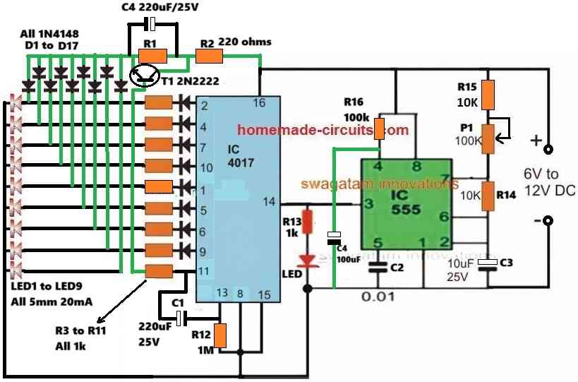
The requested circuit design of an LED light wave generator can be witnessed in the following diagram.
The working of the circuit can be understood with the following points:
Here, the IC 4017 is configured as a 9 stage sequential shift generator for switching the 9 LEDs connected across its output pins. The sequential shifting of logic high across the IC 4017 outputs happen in response to each clock pulse applied to its pin#14 by the IC 555 astable oscillator.
When power is first switched ON, the IC 555 is initially kept disabled by grounding its pin#4 reset pin through C4.
It remains disabled for a few seconds depending on the values of R16 and C4. This ensures no clock pulses are fed to the clock input pin#14 of the IC 4017, and the LED switching remains disabled.
In the meantime, the supply voltage passing through the top vertical 1N4148 diodes and the 220uF capacitor illuminate the LEDs with full brightness.
The series 220 ohm resistor limits the current to safe limits which can be altered to create an optimal 100% illumination on the LEDs during the initial power switch ON.
Once the 220uF capacitor has charged fully, the 100% illumination level on the LEDs is reduced to around 50% due to the presence of R1. R1 can be tweaked appropriately for getting the desired 50% reduced level on the LEDs.
Now, in the meantime the pin#4 of IC 555 is enabled which allows the IC 555 to oscillate freely and provide the clock pulses to pin#14 of IC 4017.
This causes the IC 4017 outputs to start sequencing with logic high outputs. Due to this, the LEDs now begin pulsing one by one from its existing 50% illumination to its full 100% illumination.
This creates a wave like simulation on the LEDs as they are pulsed from their initial dim illumination to bright illumination in a sequential manner.
This wave like effect continues until the last 8th LED on pin#9 is reached. On the next sequence at pin#11, the transistor T1 is turned ON, which yet again causes the whole LED array to switch ON brightly at its maximum brightness.
In the meantime, the high logic at pin#11 of the IC 4017 keeps the sequencing process disabled by keeping pin#13 high through C1 220uF capacitor.
The C1 value can be appropriately adjusted to hold the required 5 second full illumination on the LEDs at the end of each sequential cycle.
Once C1 is fully charged, pin#13 is released from the high logic and the IC resets and the cycle begins afresh.
The LEDs once again start switching from low brightness to high brightness intermittently creating the desired wave like LED light effect.
This concludes the article on LED light wave effect generator circuit, if you have any further doubts or questions, please do not hesitate to ask them through the comment box below.


Comments
Dear Sir,
Sorry – I meant blue LEDs which i can use in place of black colour.
Actually I am looking for a roulette circuit which will have the red and blue LEDs in circular fashion and also a digital display of the number.
I am looking out for someone who can do these for me. Do you know of anyone in Mumbai or our vicinity, please let me know. I am in vadodara.
Regards
Thank you DHSanj, got it! However at the moment I do not know anybody who can get this done for you, if I happen to find someone I’ll surely let you know.
Mr. Swagatam,
Back in December you designed this circuit for me. I am ready to get it built and installed…however, I cannot find anybody online nor in the Fort Worth-Dallas area who can build the circuit for me. Is there a website with resources I can contact to have the physical circuit built? I am mechanical, this is too tedious and beyond my skills. Your help is appreciated.
Airman Dillard
Denton, Texas
LED Light Wave Effect Generator Circuit
https://www.homemade-circuits.com/led-light-wave-effect-generator-circuit/
Hi Airman,
Sorry, unfortunately I do not seem to know anybody you can complete this project for you. Yes, the circuit is indeed complex for any newcomer in the field. I will keep looking, and if I happen to find a competent person i will surely let you know.
Dear Swagatham,
Greetings. I m seeking help for circuit a roulette wheel as a game kit with 37 LEDs, i.e. 1 green, 18 red and 18 black.
Please guide me if you have any circuit that can be made with easily available ICs in India and components without any programming.
Hi, Sanj, I do not have 37 led circuit, however I can provide an 18 led design. By the way what are black LEDs, could you please elaborate?