In this article I will comprehensively explain about the RCWL-0516 a microwave proximity motion sensor which uses Doppler radar.
Here, I will elucidate the following points:
- RCWL-0516 pinout Details.
- RCWL-0516 Circuit Working.
- How Doppler Effect Works.
- How to Connect RCWL-0516 with LED to Detect Motion.
- How RCWL-0516 can work through an Enclosure.
- How to Connect LDR with RCWL-0516.
What is RCWL-0516
It is yet another type of proximity motion sensor which can detect if someone has entered into an area, and raise an alarm or take an appropriate action.
In one of our earlier posts we have learned about PIR sensors which detected a change in the amount of infrared energy in the room and then it took action on that.
We have also learned about ultrasonic and lidar distance sensors and these can be used as a form of proximity sensor as well.
You can basically use these devices to measure the distance to an object, so someone walked into a room and you aim the sensor at them, the distance of that person would be reflected and therefore you would get a reading on that and would be able to take action.
However, the RCWL-0516 sensor we are discussing today works on a completely different principle. It actually works by detecting motion of a body using microwaves.
Is the Microwave Radiation from RCWL-0516 Harmful??
Please do not panic, we are talking about a very very low level of microwave radiation and about the 3.1 GHz microwave band.
This is perfectly safe to be working with it. It is not going to harm you even if you get very close to the sensor, so don't worry about the microwave aspect of it.
What's interesting about this RCWL-0516 sensor however is that it works on a completely different principle than the other previous types which I will explained above.
How RCWL-0516 Motion Sensor Works
It does not measure the distance to an object by reflecting a signal back, and it is certainly not measuring anything that's given of by the object.
What it is using is something called the doppler effect. Now, if you are not familiar with doppler effect, don't worry I am going to explain what that is before we start using the sensor.
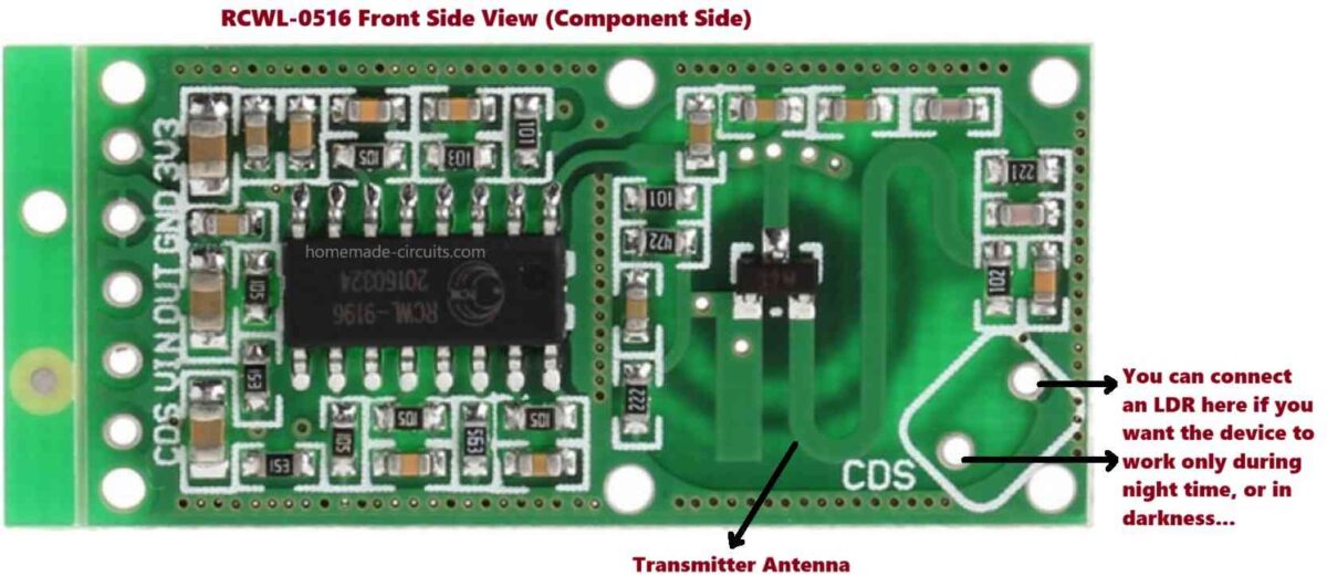
As you can see in the image the RCWL-0516 is a very tiny. It is also very very inexpensive.
Just like the infrared proximity sensor that I will explained before, this RCWL-0516 device can be used on its own.
You don't actually need to have a microcontroller with it, but if you add a microcontroller like an Arduino to it, you can give it a different functionality.
So let's now understand how the RCWL-0516 microwave proximity sensor works and also look at what doppler effect is.
First let's take a closer look at the RCWL-0516 device.
This tiny device is a microwave proximity sensor.
It operates with a supply input range of 4V to 28V DC, making it ideal for battery powered equipment.
It also has a built-in 3.3 V voltage regulator, which can supply up to a 100 mA for external logic circuitry.
It works approximately with a frequency of 3.18 GHz.
The device uses doppler radar to detect motion.
RCWL-0516 Pinout Details


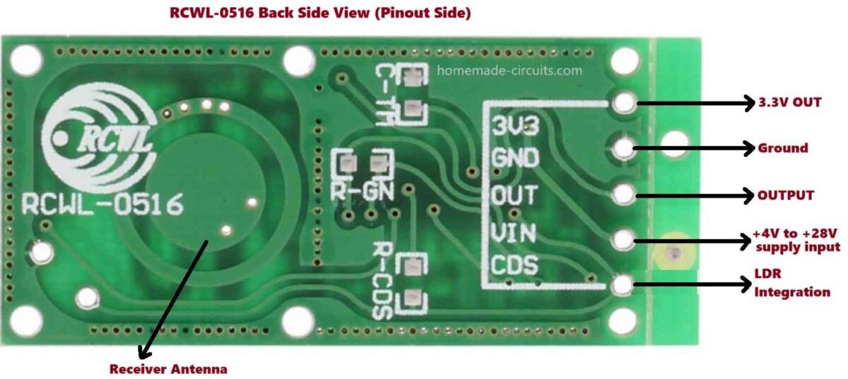
Referring to the above figures of the RCWL-0516 motion sensor module, the pinouts details can be understood as given below:
1) The 3V3 pinout is the 3.3 V output. Make sure you don't mistake it as a voltage input.
2) The GND pinout is obviously the ground pin.
3) OUT is the digital output. This pinout has a 3.3 V logic signal which will go high fo 2 seconds if an object is detected.
4) VIN pinout is for the power supply input voltage between +4V and +28V DC.
5) The CDS pinout connection is on two places on this board. This pinout is for connecting an external LDR, to turn the device OFF when there is ample ambient light available in the premise.
Understanding Doppler Effect
The working of the RCWL-0516 device is based on Doppler radar, which makes use of the Doppler effect.
The Doppler effect was discovered in 1842 by an Austrian physicist Christian Doppler.
It describes a change in frequency that's observed by a stationery observer when the source of the frequency is moving.
The Doppler effect applies to all forms of waves including light, sound, radio and water.
Now, here's an illustration of how Doppler effect works.
Imagine a train that has a whistle frequency of 1000 Hz.
Right now our train is stationery.
Let's bring in an observer. Since the train is stationery, the observer will also hear the train whistle at the same 1000 Hz.
Now, let's imagine our train starts moving forward.
When the train is moving forward, the whistle waves in front of the train will get compressed, while the waves behind the train will be expanded.
Our observer, who has the train coming toward him will begin hearing the waves at a relatively higher frequency.
Now, let's stop the train and move our observer behind the train.
Let the train start moving again with a whistle frequency of 1000 Hz.
However since the whistle waves is getting expanded behind the train, our observer now hears it with a lower frequency, as the train moves away from him.
This is the Doppler effect.
In radar application we can measure the velocity of distant objects using the Doppler effect.
And this how the RCWL-0516 module operates.
Originally you won't see any terminals or leads soldered on it, and the connections are all at the bottom side of the board.
On turning the board, on the other side we find on one side they have got a circle, which is one of the antennas, and on the other side they have some lines which forms the other antenna.
Possibly, these lines work as the transmitter antenna, while the circle on the other side work like the receiving antenna.
We can see the connections at the bottom, and there are also some connections at the top, this is where you can connect the light sensitive cell if you want to use that.
How to Use RCWL-0516 (Testing with an LED)
Now I will explain how to use the RCWL-0516 microwave sensor practically.

Parts List
- Resistor 1k 1/4 watt = 1
- 3.3 V 20 mA LED = 1
- RCWL-0516 Module = 1
- 12V DC Power supply or Battery = 1
- Connecting wires.
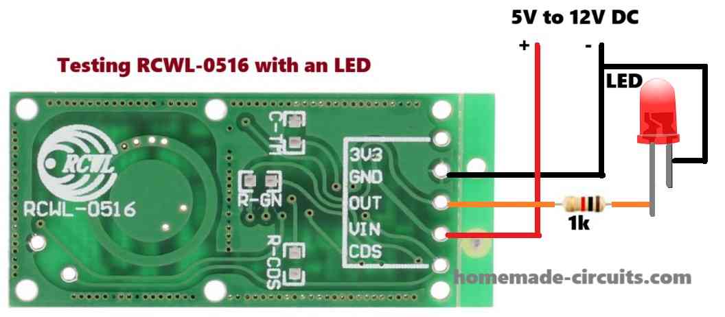
For our first experiment we will test the RCWL-0516 microwave motion sensor module with an LED, as depicted in the above figure.
We will also need a current limiting resistor for the LED, which can be any value between 470 ohms and 1k. We will also need a power supply which can be a constant 5V DC power supply.
Begin by connecting the +5V or +12V of the power supply to the Vin input on the RCWL-0516 board.
Connect the negative of the power supply to the ground pin of the RCWL-0516 module.
Connect one end of the limiting resistor with the anode of the LED.
Connect the other end of the limiting resistor to the output terminal of the RCWL-0516 board.
Finally, connect the cathode of the LED to the ground of the power supply.
This completes the basic LED wiring with the RCWL-0516 board.
Once the above connections are done and power supply switched ON, any movement made by you in the room will trigger ON the LED, and you will find the response to be extremely sensitive.
You will also find that by angling it you could change the sensitivity, so to ensure optimal sensitivity it is important to aim the RCWL-0516 module where you want the device to sense the motion of an object.
RCWL-0516 can Detect Motion Through a Plastic Cover
One thing appears to be interesting, that is when you enclose the RCWL-0516 board with a plastic cover, it is still able to detect the motion, since the RCWL-0516 is able to detect motion even through the plastic cover quite easily.
So this feature is very useful when you want to use this RCWL-0516 microwave sensor in locations where it could get wet or exposed to bad weather.
You could enclose it inside a box and yet it would be as sensitive.
Thus, wiring the RCWL-0516 microwave sensor is very simple as I will explained above.
How to Connect an LDR with RCWL-0516
Now, I will explain how a light sensitive resistor or an LDR can be added to this module.
In our next experiment, we will use the same wiring connections as above.
Here, we are going to add one more component, a light dependent resistor (LDR).
We will connect the LDR across the CDS terminals of the RCWL-0516.
The following figure shows the entire setup using an LED, LDR and the RCWL-0516 module.

You will find that as long there's ample ambient light present in the room, the RCWL-0516 does not respond to your movements and the LED remains completely shut off.
However, once you turn off the lights and the room becomes completely dark, the RCWL-0516 quickly starts responding to your movements, illuminating the LED as a result.
This feature is excellent for applications where you only want to detect movement in dark. And using an ordinary LDR makes this possible very easily.
How to Connect RCWL-0516 with a Relay for Switching AC 220V Loads
In the above sections I will explained how to test the RCWL-0516 microwave motion sensor using an LED and LDR.
However, if you want the microwave motion sensor RCWL-0516 to switch ON/OFF an AC 220V load through a relay, you can configure the device with a relay as depicted in the following diagram:

Parts List
- 4.7k 1/4 watt resistor = 1
- Transistor BC547 = 1
- 3.3 V 5 mA LED = 1
- Diode 1N4007 = 1
- 12V, 5-pin Relay = 1
- RCWL-0516 Module = 1
- 12V Power Supply = 1
- Connecting wires.
Warning: Wiring the 220V load with the relay may be exposed to lethal AC mains voltage. Extreme caution must be exercised while testing and connecting these wiring.
Applications
The basic working of the RCWL-0516 as explained above can be used in applications such as a door bell where you want to trigger a bell when someone comes near the door. Or you can use it as a burglar alarm to trigger an alarm when an intruder is detected in the premise.
Hi, Can 5V relay module be connected directly to RCWL-0516? -Thanks!
Hi, If the module has a relay driver transistor, then it can be integrated directly with the RCWL-0516.
Hi Swagatam, I am interested in the last circuit. The rcwl0516 is used to switch a relay. I have a similar circuit that I am supplying 12v to a cd4060 and I am using the output of the rcwl0516 to switch a npn transistor which grounds pin 12 of the cd4060 to begin its oscillations. It appears that the transistor is not switching (turning on). Your circuit has an LED between the rcwl0516 output and the transistor. Is this LED required? My experiences have been that 3.3v will not switch 12v. Maybe I am confused. Please explain. Thanks!
Hi Norman,
The LED is just for indication purpose, to show that the output of the rcwl0516 is ON.
You are right, if the output from the rcwl0516 is 3.3V then the series LED might completely block it, causing the transistor to remain switched OFF.
You can remove the LED, and replace it with a short, or replace it with a 1.5V LED.
The Quantum Initiative 2017, whitehouse.gov was looking for quantum sensors to expand the science. are these communities in communication with each other? Because I think you may be talking about the same thing. I myself am looking for directions to set up a free energy array, ala Tartaria.
Can you please elaborate?
Tartaria was a land in Eastern Europe that had free energy and moving sidewalks and automobiles. Like the USA had in the 17 or 1800s.
Churches were built with elaborate windows and resonance Chambers. With steeples high in the air and every home seem to have steeples or antennas.
Findhorn garden was renowned for its huge vegetables. They used electro culture similar to Tesla technology. On a large scale you could energize a city and more.
Does this help?