• Skip to main content
  • Skip to primary sidebar

Homemade Circuit Projects

Need circuit help? Post them in the comments! I've answered over 50,000!

Blog | Categories | About | Hire Me | Contact | Calculators-online
You are here: Home / Boost Converter Calculator (Non-Isolated)

Boost Converter Calculator (Non-Isolated)

This calculator will help you to design and find the optimal inductor value for a non-isolated boost (step-up) converter circuit, ensuring that your circuit works with an efficient operation with a 30% ripple current.
Boost Converter Inductor Calculator

Calculates required inductance assuming an ideal converter and a 30% target ripple current.

Results:

Duty Cycle (D): 0 %

Estimated Input Current (Iin): 0 A

Optimal Inductor Value (L): 0 µH

Calculator by homemade-circuits.com

How to Use the Boost Converter Inductor Calculator

Steps to Use:

Enter the Input Voltage (Vin) = The voltage from your power source which you want to boost (e.g lets say 12V).
Enter the Output Voltage (Vout) = The desired boosted voltage value which you want at the output (e.g let us say 220V).
Enter the Switching Frequency (kHz) = The PWM switching frequency of your astable multivibrator circuit (e.g you can set it up to work with 50 kHz).
Enter the Output Current (A) = The expected load current, which you want to supply the connected load at the output (e.g 1A).
Click the "Calculate" Button = The results will then show up in the relevant fields:

  • Duty Cycle (%) = How long the switch stays ON in one cycle.
  • Optimal Inductor Value (µH) = The required inductor size for stable operation.

Example Calculation

Given:

  • Vin = 12 V
  • Vout = 220 V
  • f = 50 kHz = 50,000 Hz
  • Iout = 1 A

Step 1: Duty Cycle (D)

Formula:

D = 1 − (Vin / Vout)

Substituting:

D = 1 − (12 / 220)
= 1 − 0.054545
= 0.945455

Therefore....

D = 94.55%

Step 2: Estimated Input Current (Iin)

Formula:

Iin = Iout / (1 − D)

Substituting:

Iin = 1 / (1 − 0.945455)
= 1 / 0.054545
= 18.33 A

Therefore,

Iin ≈ 18.33 A

Step 3: Ripple Current (ΔIL)

If "Input Current (Recommended)" is selected:

ΔIL = 0.3 × Iin
= 0.3 × 18.33
= 5.50 A

Step 4: Inductor Value

Formula:

L = (Vin × D) / (ΔIL × f)

Substituting:

L = (12 × 0.945455) / (5.50 × 50,000)
= 11.345 / 275,000
= 0.00004125 H

Therefore,

L = 41.25 µH

Final Results (Using Ripple Based on Iin)

  • Duty Cycle: 94.55%
  • Estimated Input Current: 18.33 A
  • Ripple Current: 5.50 A
  • Optimal Inductor: 41.25 µH

As you can see, the duty cycle is so high at 95% which is a bad thing, so boosting voltage with this circuit from 12V to 220V looks like a bad idea.

So better to go with flyback SMPS topology instead.

Reader Interactions

Questions & Answers

Total Posts: 8
Newest Oldest
vyas
July 12, 2025 • 1 year ago #184401

I am not a electronic student and a chemistry student. Hence I asked you to give me circuit schematic so that I could directly jump into my experiments. I have a TV LOT of ferrite core and 28 K V output. More over it has a diode builtin its output. So I thought I will wind some wire on the core and get the required voltage.
SO try to understand my problem and give me solution.
Thanks and best regards.

Reply
SwagatamAdmin
July 12, 2025 • 1 year ago #184402

Vyas, I do not know much about the ferrite core used in TV LOT coil, and have no such calculator to calculate a LOT winding.
If you can use a standard ferrite E-core for your boost converter then I can probably help.

Reply
David
July 14, 2025 • 1 year ago #184448

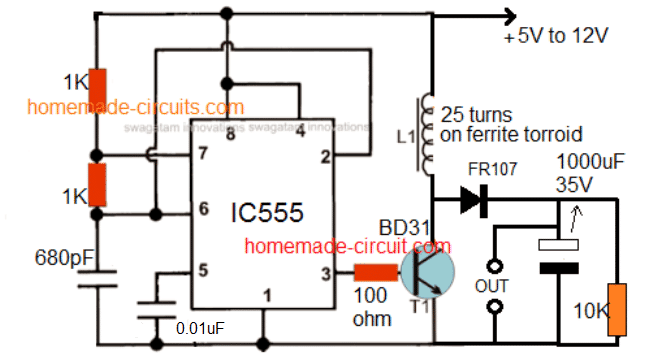
I can’t find BD31 for sale. Is the part number correct?

Reply
SwagatamAdmin
July 14, 2025 • 1 year ago #184458

The transistor number is not critical, you can try any transistor of your choice by appropriately matching the parameters.

Reply
NgPark
February 17, 2026 • 8 months ago #201221

Hello Mr. Swagatam, thank you so much for everything you do for us. We are becoming increasingly skilled and very confident in this field of electronics thanks to you and your expertise. But currently, my biggest problem is this: I still haven’t managed to properly size the complete winding of a switching power supply.

Reply
SwagatamAdmin
February 17, 2026 • 8 months ago #201226

Hello NgPark,
Thank you for your kind words, I am glad you found my circuits helpful..
Can you please tell me which circuit and topology have you tried, and what kind of difficulties are you facing? I will try my best to sort it for you…please let me know..

Reply
Ola
June 23, 2026 • 3 months ago #208785

Please (1) what is the output voltage of this boost converter circuit and (2) where is the battery negative input voltage terminal,only the battery positive terminal voltage (+5 to 12) is indicated in the circuit.I mean where can I connect battery negative wire to for input voltage

Reply
SwagatamAdmin
June 23, 2026 • 3 months ago #208792

You have to decide what output voltage you want…and then calculate accordingly…
The pin#1 line of IC 555 is the ground line or the battery negative line…

Reply

Need Help? Please Leave a Comment! We value your input—Kindly keep it relevant to the above topic! Cancel reply

Your email address will not be published. Required fields are marked *

Primary Sidebar

My YouTube Channel

Circuit Simulator: Draw and Simulate Schematics

circuit simulator image

Categories

  • Arduino Projects (95)
  • Audio and Amplifier Projects (134)
  • Automation Projects (18)
  • Automobile Electronics (104)
  • Battery Charger Circuits (90)
  • Datasheets and Components (109)
  • Electronics Theory (151)
  • Energy from Magnets and Earth (43)
  • Games and Sports Projects (11)
  • Grid and 3-Phase (20)
  • Health related Projects (27)
  • Home Electrical Circuits (13)
  • Indicator Circuits (16)
  • Inverter Circuits (98)
  • Lamps and Lights (161)
  • Meters and Testers (72)
  • Mini Projects (28)
  • Motor Controller (68)
  • Oscillator Circuits (30)
  • Pets and Pests (15)
  • Power Supply Circuits (91)
  • Remote Control Circuits (50)
  • Security and Alarm (65)
  • Sensors and Detectors (107)
  • SMPS and Converters (46)
  • Solar Controller Circuits (62)
  • Temperature Controllers (44)
  • Timer and Delay Relay (51)
  • Voltage Control and Protection (44)
  • Water Controller (37)
  • Wireless Circuits (31)

Subscribe to get New Circuits in your Email

Other Links

  • Privacy Policy
  • Cookie Policy
  • Disclaimer
  • Copyright
  • Videos
  • Sitemap

People also Search

555 Circuits | 741 Circuits | LM324 Circuits | LM338 Circuits | 4017 Circuits | Ultrasonic Projects | SMPS Projects | Christmas Projects | MOSFETs | Radio Circuits | Laser Circuits | PIR Projects |

Recent Comments

  • Swagatam on DC to DC Converter Circuits using SG3524 [Buck, Boost Designs]
  • Swagatam on 3 Best Joule Thief Circuits
  • Swagatam on EGS002 Datasheet, Circuit Diagram Explained
  • Swagatam on Vehicle Parking Lot Counter Circuit
  • Swagatam on Smart Emergency Lamp Circuit with Maximum Features

Social Profiles

  • Twitter
  • YouTube
  • Instagram
  • Pinterest
  • My Facebook-Page
  • Stack Exchange
  • Linkedin

Calculators

  • ZVS Induction Heater + Tank Calculator Tool
  • Zener Diode Calculator
  • Wire Current and Thickness Calculator (Ampacity Calculator)
  • Voltage Divider Calculator
  • Transistor Base Resistor Calculator
  • Transistor Astable Multivibrator Calculator
  • TL431 Calculator
  • Solar Panel, Inverter, Battery Calculator
  • Ferrite Core Air Gap Calculator Tool
  • Parallel MOSFET Calculator Tool: How to Connect MOSFETs in Parallel Safely
  • LC Resonance Calculator for EV Battery Charger Circuits
  • LED String Series Resistor Calculator
  • PFC (Power Factor Correction) Calculator Tool: 3kW
  • Passive Power Factor Correction (PFC) Calculator
  • LM567 IC Calculator Tool
  • SMPS Flyback Boost Converter Calculator
  • Shunt Resistor Calculator for Ammeters
  • SCR and Triac Gate Resistor Calculator
  • Battery Back up Time Calculator
  • Boost Converter Calculator (Non-Isolated)
  • Bootstrap Capacitor Calculator
  • Buck Converter Calculator
  • Buck-Boost Converter Calculator
  • Capacitance Reactance Calculator
  • DCM Flyback Transformer & Wire Gauge Wire Size Calculator Tool
  • Filter Capacitor Calculator
  • IC 4047 Calculator (Frequency and PWM)
  • IC 4060 Calculator
  • IC 555 Astable Calculator
  • IC 555 Monostable Calculator
  • IC SG3525, SG3524 Calculator
  • Inductance Calculator
  • Induction Heater Inductor and Resonant Frequency Calculator
  • Induction Heater Work Coil Calculator
  • Inverter LC Filter Calculator
  • LC Resonance Calculator
  • LED Current Calculator
  • LM317, LM338, LM396 Calculator
  • NAND/NOT Gate RC Values Calculator
  • NOT, NAND Gate Frequency Calculator
  • Notch Filter Calculator Tool
  • Ohm’s Law Calculator
  • Phase Angle Phase Shift Calculator
  • Power Factor (PF) Calculator
  • RC Filter Calculator
  • Reactance Calculator
  • Sine Table Calculator for SPWM Arduino Code
  • Small Signal Transistor(BJT) and Diode Quick Datasheet
  • SMPS Calculator for Toroidal Ferrite Transformers
  • SMPS Flyback Transformer Calculator – Design by Target Duty Cycle
  • TL431 Calculator
  • Op-Amp Hysteresis Resistor Calculator

© 2026 · Swagatam Innovations