In this post I have explained about a few easy to build, compact 1 watt LED bulb circuits. The first circuit is SMPS based, the second design uses a capacitive power supply, while the remaining concepts show how to used a DC source to illuminate a 1 watt LED.
Warning: Many of the circuits I have explained below are not isolated from mains AC, and therefore are extremely dangerous to touch in the powered and open condition. You should be extremely careful while building and testing these circuits, and make sure to take the necessary safety precautions. The author cannot be held responsible for any mishap due to any negligence by the user
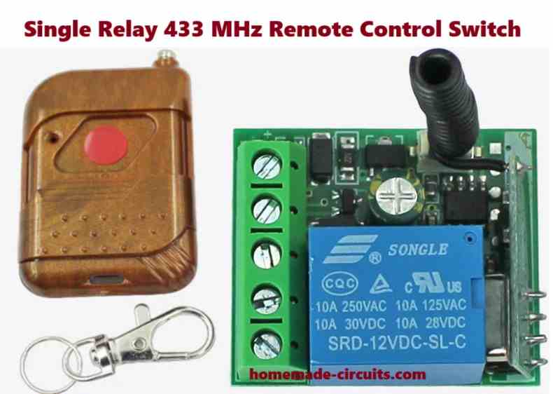
1) Small 1 watt SMPS LED Driver
In the first design which is the most recommended one, we study an SMPS LED driver circuit which can be used for driving high watt LEDs rated anywhere between 1 watt LED upto 12 watts. It can be directly driven from any domestic 220V AC or 120V AC mains outlets.
Introduction
The first design explains a small non isolated SMPS buck converter design (non-isolated Point of Loads), which is very accurate, safe and easy to build circuit. I have explained the details.
You may also want to learn How to Design LED Driver Circuits
Main Features
The proposed smps LED driver circuit is extremely versatile and specifically suited for driving high watt LEDs.
However being a non-isolated topology does not provide safety from electric shocks at the LED side of the circuit.
Apart from the above drawback, the circuit is flawless and is virtually protected from all possible mains surge related dangers.
Although a non-isolated configuration may look a bit undesirable, it relieves the constructor from winding complex primary/secondary sections on E-cores, since the transformer here is replaced with a couple of simple ferrite drum type of chokes.
The main component here responsible for the execution of all the features is the IC VIPer22A from ST microelectronics, which has been specifically designed for such small transformerless compact 1 watt LED driver applications.
Circuit Diagram
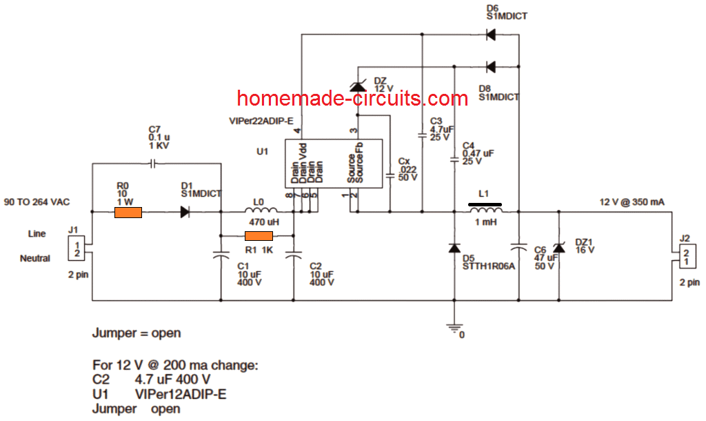
Image Courtesy: © STMicroelectronics - All rights reserved
Circuit Operation
The circuit functioning of this 1 watt to 12 watt LED driver can be understood as given under:
The input mains 220V or 120V AC is half wave rectified by D1 and C1.
C1 along with the inductor L0 and C2 constitute a pie filter network for cancelling EMI disturbances.
D1 should be preferably replaced with two diodes in series for sustaining the 2kv spikes bursts generated by C1 and C2.
R10 ensures some level of surge protection and acts like a fuse during catastrophic situations.
As can be seen in the above circuit diagram, the voltage across C2 is applied to the internal mosfet drain of the IC at pin5 to pin8.
An inbuilt constant current source of the VIPer IC delivers a 1mA current to pin4 of the IC which is also the Vdd pin of the IC.
At about 14.5V at Vdd, the current sources gets switched OFF and forces the IC circuitry into an oscillatory mode or initiates pulsing of the IC.
The components Dz, C4 and D8 become the circuit regulation network, where D8 charges C4 to the peak voltage in the freewheeling period and when D5 is forward biased.
During the above actions, the source or the reference of the IC is set to about 1V below ground.
For a comprehensive info about the circuit details of the 1 watt to 12 watt LED driver, please go through the following pdf datasheet by ST microelectronics.
2) Using Transformerless Capacitive Power Supply
The next 1 watt LED driver I have explained below shows how to build a few simple 220 V or 110 V operated 1 watt LED driver circuit,that would cost you not more 1/2 a dollar, excluding the LED of course.
I have already discussed capacitive type of power supply in a couple posts, like in LED tube light circuit and in a transformerless power supply circuit, the present circuit also utilizes the same concept for driving the proposed 1 watt LED.
Circuit Operation
In the circuit diagram we see a very simple capacitive power supply circuit for driving a 1 watt LED, which may be understood with the following points.
The 1uF/400V capacitor at the input forms the heart of the circuit and functions as the main current limiter component of the circuit. The current limiting function makes sure that the voltage applied to the LED never exceeds the required safe level.
However high voltage capacitors have one serious issue, these do not restrict or are not able to inhibit the initial switch ON mains power in rush, which can be fatal for any electronic circuit LEDs are no exceptions.
Adding a 56 Ohm resistor at the input helps to introduce some damage control measures, but still it alone cannot do the complete safeguarding of the involved electronics.
An MOV would certainly do, also what about a thermistor? Yep, a thermistor would also be a welcome proposition.
But these are relatively at the costlier side and we are discussing a cheap version for the proposed design, so we would want to exclude anything that would cross a dollar mark as far as the total cost goes.
So I thought of an innovative way of replacing an MOV with an ordinary, cheap alternative.
What is the function of an MOV
It's to sink the initial burst of high voltage/current to ground such that it is ground before reaching the LED in this case.
Wouldn't a high voltage capacitor do the same function if connected across the LED itself. Yes it would surely operate the same way as an MOV.
The figure shows the insertion of another high voltage capacitor directly across the LED, which sucks the instantaneous influx of voltage surge during power switch ON, it does this while charging up and thus sinks almost the entire initial voltage in rush making all the doubts associated with a capacitive type of power supply distinctly clear.
The end result as shown in the figure is a clean, safe, simple and a low cost 1 watt LED driver circuit, which can be built right at home by any eletronic hobbyist and used for personal pleasures and utility.
CAUTION: THE CIRCUIT SHOWN BELOW IS NOT ISOLATED FROM THE AC MAINS, THEREFORE IS EXTREMELY DANGEROUS TO TOUCH IN POWERED POSITION.
Circuit Diagram
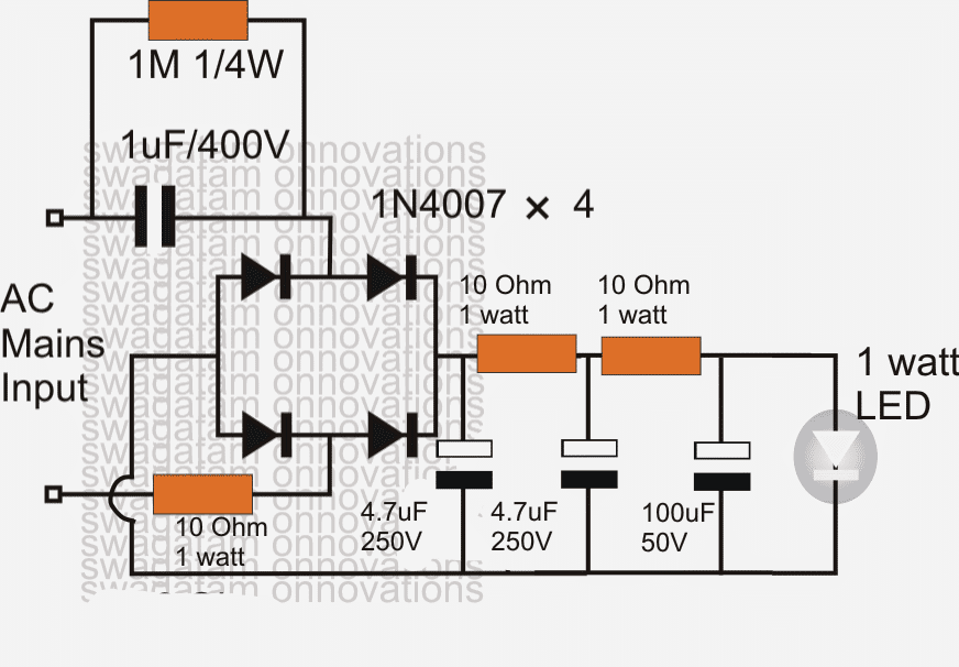
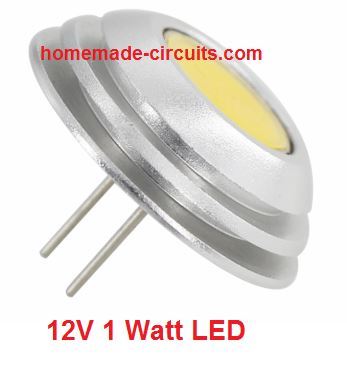
NOTE: The LED in the above diagram is a 12V 1 watt as shown below:
In the above shown simple 1 watt led driver circuit, the two 4.7uF/250 capacitors along with the 10 ohm resistors form a kind of "speed breaker" in the circuit, this approach helps to arrest the initial switch ON surge inrush which in turn helps to safeguard the LED from getting damaged.
This feature can be replaced with an NTC which are popular for their surge suppressing features.
This enhanced way of tackling the initial surge inrush problem could be by connecting an NTC thermistor in series with the circuit or the load.
Please check out the following link for knowing how to incorporate an NTC thermister in the proposed 1 watt LED driver circuit
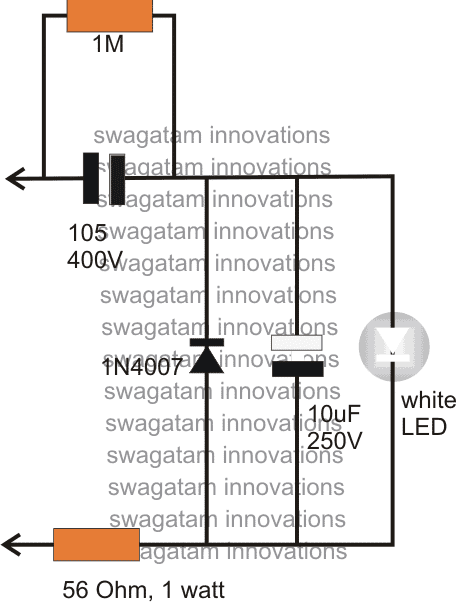
The above circuit can be modified in the following manner, however the light may be a little compromised.
A good way of tackling the initial surge inrush problem is by connecting an NTC thermistor in series with the circuit or the load.
Please check out the following link for knowing how to incorporate an NTC thermister in the proposed 1 watt LED driver circuit
https://www.homemade-circuits.com/2013/02/using-ntc-resistor-as-surge-suppressor.html
3) A Stabilized 1 watt LED Driver using Capacitive Power Supply
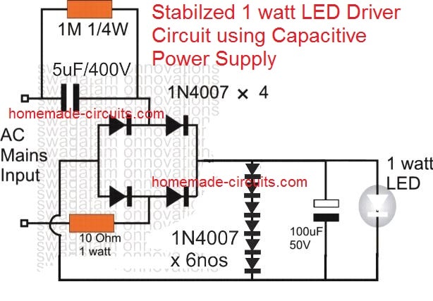
As can be seen, 6nos of 1N4007 diodes are used across the output, in their forward biased mode. Since each diode would produce a drop of 0.6V across itself, 6 diodes would create a total drop of 3.6V, which is just the right amount of voltage for the LED.
This also means that the diodes would shunt the rest of the power from the source tp ground, and thus keep the supply for the LED perfectly stabilized and safe.
Another Stabilized 1 watt Capacitive Driver Circuit
The following MOSFET controlled design is probably the best universal LED driver circuit that guarantees a 100% protection for the LED from all types of hazardous situations, such as sudden over voltage and over current or surge current.
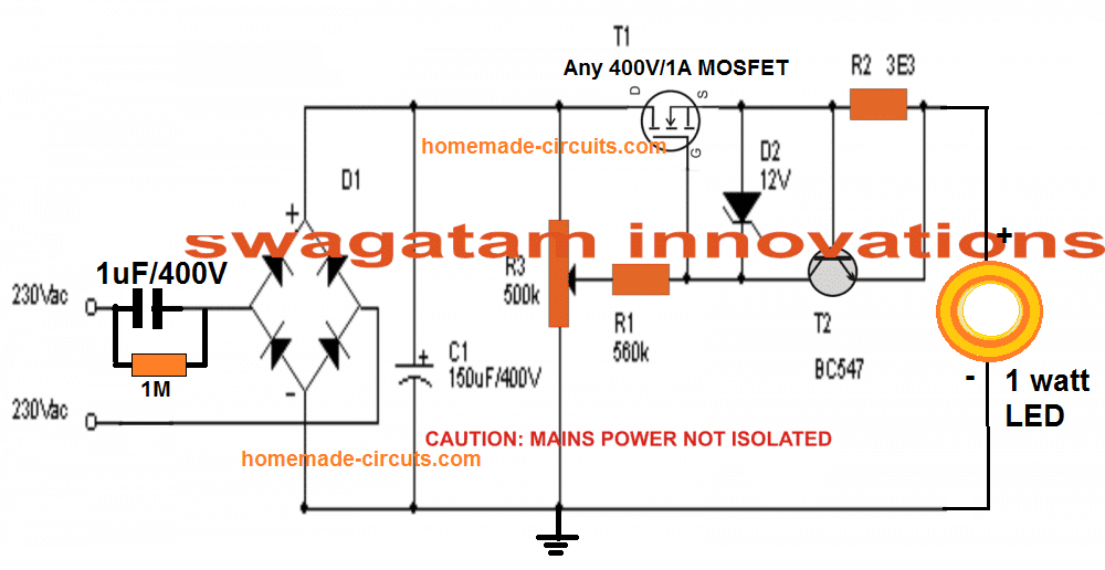
A 1 watt LED connected with the above circuit would be able to produce around 60 Lumens of light intensity, equivalent to a 5 watt incandescent lamp.
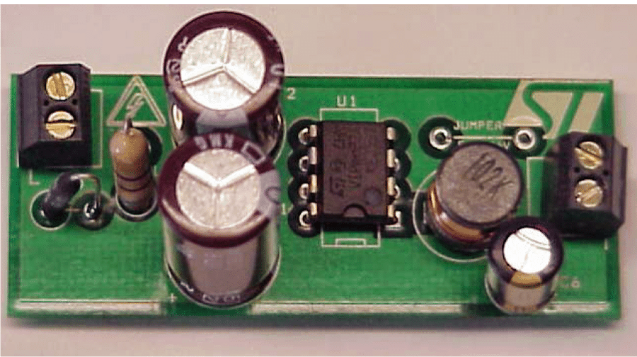
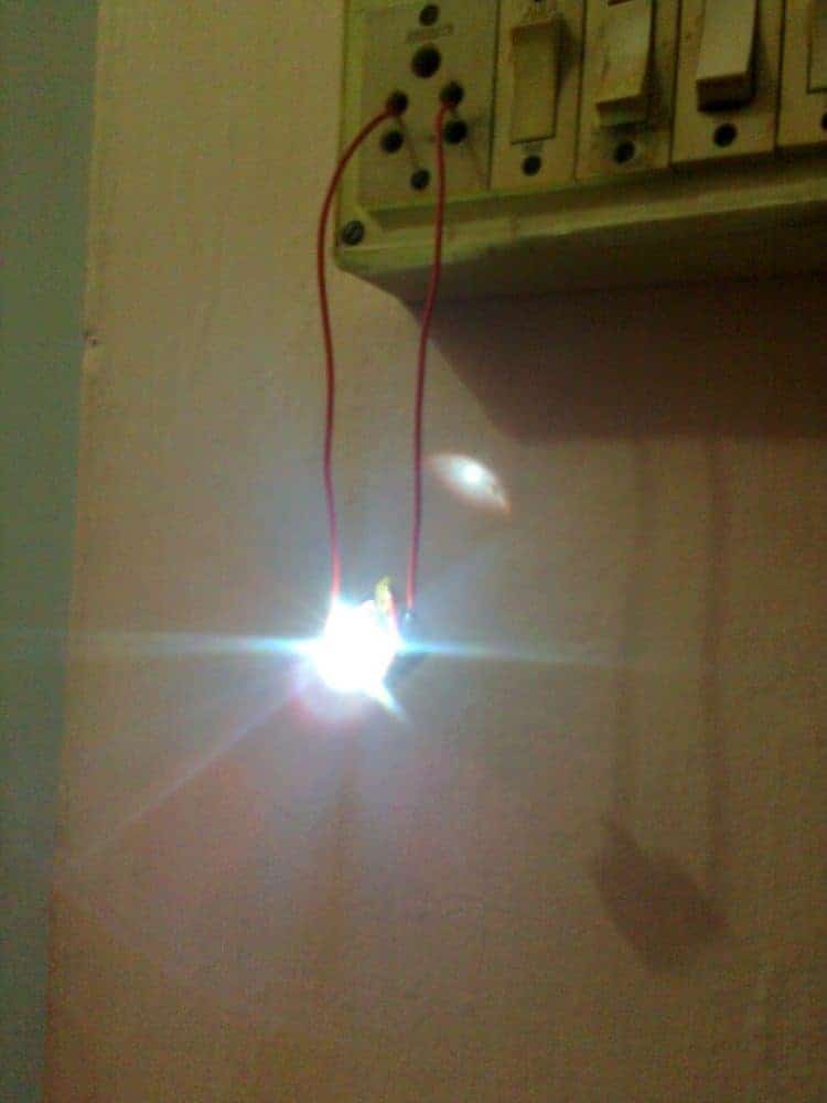
Prototype Images

The above circuit can be modified in the following manner, however the light may be a little compromised.
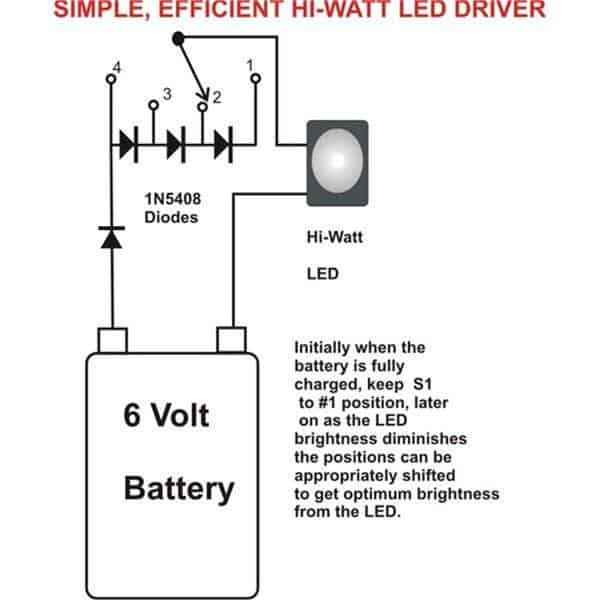
4) 1 Watt LED Driver Circuit Using a 6V Battery
As can be seen in the fourth diagram, the concept hardly utilizes any circuit or rather does not incorporate any hi-end active component for the required implementation of driving a 1 watt LED.
The only active devices that's been employed in the proposed simplest 1 watt LED driver circuit are a few diodes and a mechanical switch.
The initial 6 volts from a charged battery is dropped to the required 3.5 volts limit by keeping all the diodes in series or in the path of the LED supply voltage.
Since each diode drops 0.6 volts across it, all four together allow only 3.5 volts to reach the LED, lighting it safely, yet brightly.
As the illumination of the LED drops, each diode is bypassed subsequently using the switch, to restore the brightness of the LED.
The use of the diodes for dropping the voltage level across the LEDs makes sure that the procedure does not dissipate any heat and therefore becomes very efficient in comparison to a resistor, which would have otherwise dissipated a lot of heat in the process.
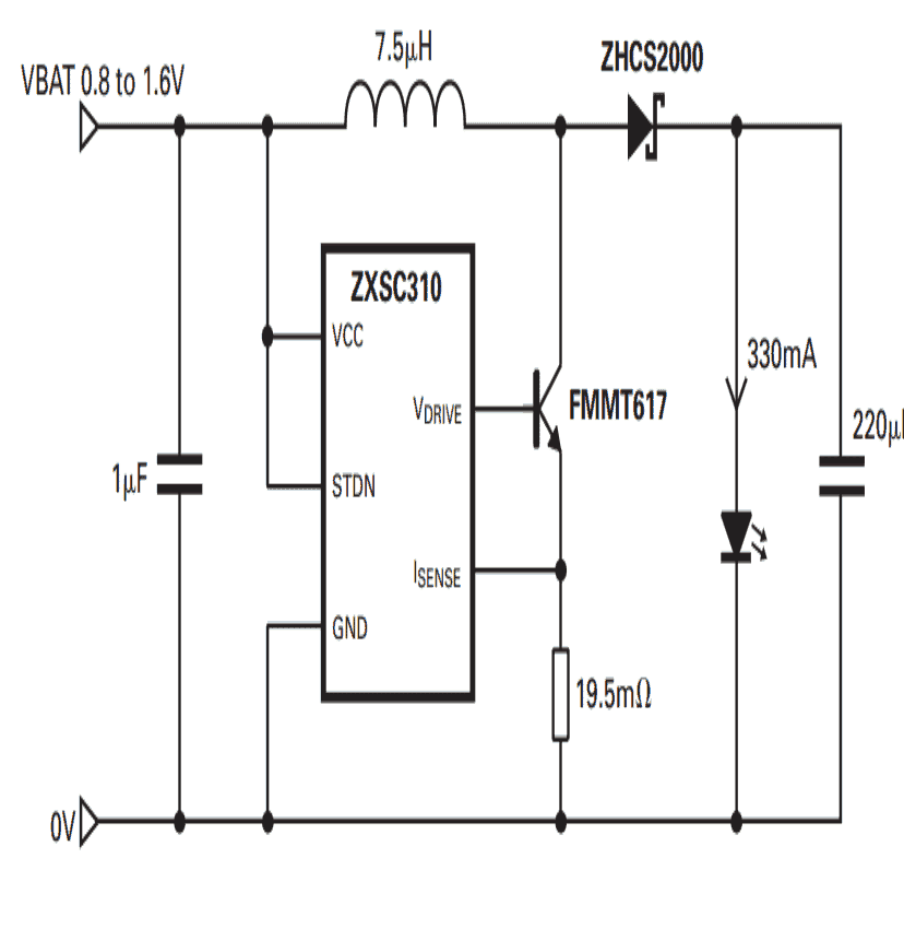
5) Illuminate 1 Watt LED with a 1.5V AAA Cell
In the 5th design I have explained how to illuminate a 1 watt LED using a 1.5 AAA cell for a reasonable amount of time.The circuit is obviously based on boost driver technology, other wise driving such a huge load w such minimal source is beyond imagination.
A 1 watt LED is relatively huge when compared to a 1.5 V AAA cell source.
A 1 watt LED needs minimum 3 volts supply which is double the above cell rating.
Secondly a 1 watt LED would require anywhere between 20 to 350 mA of current for operating, 100 mA being a respectable current for driving these light machines.
Therefore using a AAA penlight cell for the above operation looks very remote and out of question.
However the discussed circuit here proves all of us wrong and successfully drives a 1 watt LED without much complications.
THANKS TO ZETEX, for providing us with this wonderful little IC ZXSC310, which requires just a few ordinary passive components for making this feat possible.
Circuit Operation
The diagram shows a rather simple configuration, which is basically a boost converter set up.
The input DC of 1.5 volts is processed by the IC to generate a high frequency output.
The frequency is switched by the transistor and the schottky diode via the inductor.
The rapid switching of the inductor provides the required boost in the voltage which becomes just appropriate for driving the connected 1 watt LED.
Here, during the completion of each frequency, the equivalent stored energy inside the inductor is pumped back into the LED generating the required voltage boost, which keeps the LED illuminated for long hours even with a source that's as small as a 1.5 volt cell.
Prototype image

1 Watt Solar LED Driver
This is school exhibition project which can be used by children to show how solar energy can be used for illuminating a 1 watt LED.
The idea was requested by Mr. Ganesh, as given below:
Hi Swagatam, I have come across your site and find your work very inspiring. I am currently working on a Science, Technology, Engineering and Math (STEM) program for year 4-5 students in Australia. The project focuses on increasing children’s curiosity about science and how it connects to real-world applications.
The program also introduces empathy in the engineering design process where young learners are introduced to a real project (context) and engages with their fellow school peers to solve a worldly problem. For the next three years, our focus is on introducing children to the science behind electricity and the real-world application of electrical engineering. An introduction to how engineers solve real-world problems for the greater good of society.
I am currently working on online content for the program, which will focus on young learners(Grade 4-6) learning the basics of electricity, in particular, renewable energy, i.e. solar in this instance. Through a self-directed learning program, children learn and explore about electricity and energy, as they are introduced to a real-world project, i.e. providing lighting to children sheltered in the refugee camps around the world. On completion of a five-week program, children are grouped in teams to construct solar lights, which are then sent to the disadvantaged children around the world.As a not 4 profit educational foundation we are seeking your assistance to layout a simple circuit diagram, which could be used for the construction of a 1 watt solar light as practical activity in class. We have also procured 800 solar light kits from a manufacturer, which the children will assemble, however, we need someone to simplify the circuit diagram of these light kits, which will be used for simple lessons on electricity, circuits, and calculation of power, volts, current and conversion of solar energy to electrical energy.
I look forward to hearing from you and keep on with your inspiring work.
The Circuit Design
Whenever a simple yet safe solar controller is required we inevitably go for the ubiquitous IC LM317. Here too, we use the same inexpensive device for implementing the proposed 1 watt LED lamp using a solar panel.
The complete circuit design can be seen below:
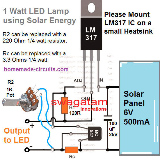
A quick inspection reveals that if a current control is present, voltage regulation can be ignored. Here's a simplified version for the above concept, using only a current limiter circuit.


Comments
Hi engineer
Thank you for your valuable content and good circuits
If possible, put the 5V 2A circuit on your website, thanks
Thank you Borhan, you can refer to the following concept and with slight adjustment convert it into a 5v smps
https://www.homemade-circuits.com/12v-2-amp-smps-circuit/
You diagram at the top of the page seems to have the same kind of chip (I think). All the “drain” pins are 0 ohms in between and the same with the source pins. I can’t quite follow where/what the input pins are and what are output. I’d like to measure and see if I’m getting anything through the chip. What should I be seeing where if the chip is the same pinout as the one about.
Also, just to clarify, I believe that blue circle part is a capacitor, but is there anything special about it? I’m getting about 170vdc on one side of it from the – side of the bridge circuit and nothing on the other.
I appreciate your help with this. I’ve contacted the distributer of the bulb and asked about getting info on the chip.
The image at the top has a VIPER22A IC which is explained in the article, your chip is completely different, all chips have different and unique specifications, they can never be similar with their functioning and pinouts.
If the blue one is a capacitor then there’s nothing special about it, a capacitor is a capacitor after all.
Here are the pictures again with some more.
https://photos.app.goo.gl/W6bdSJ31NhPecLpf9
As I said the chip says ATC9307E, but I can’t find a datasheet.
OK thanks for the information and the images. I also tried to find the datasheet but could not find any information about this IC, so it seems there’s no possibility of getting a replacement.
The only vulnerable parts (to me) are that chip and the diode at the DC end. I’m getting DC out from the rectifier from main AC. I’m getting some voltages around the chip, but not knowing the chip, I’m not sure where to go from there. The capacitors “look” ok. Not bubbled.
Yes the IC is the most vulnerable part, and this could be replaced for verifying the working of the SMPS. However, if you do not have the number of the chip printed on the chip, then it would be impossible to find a new replacement, because all ICs have different numbers and pinout specifications
I have a multimeter and an oscilloscope. I’m lost when I get to that chip though. If you can get me around there, that would help. It starts with a bridge rectifier coming through a fuseable resister from the mains and then heads over to that chip and that transformer, but I don’t understand the purpose of the transformer after the rectifier circuit.
The image you sent is no longer available. I guess the transformer after the bridge could be a filter or a choke. The other bigger transformer is the main SMPS transformer.
Ok, so perhaps maybe I should approach this from a different direction. I have several of these bulbs and the power supplies are going bad so I wanted to come up with a better solution. Maybe if you could have a look at the power supply board you could help me fix and repair them. They are using a chip ATC9307E 4-CMAP03 that I can’t find any info on. It’s an 8 pin chip. Here’s a link to photos of the power board. https://photos.app.goo.gl/xvJNcDkahobfd9pf8 I appreciate any help you can give me on troubleshooting as these bulbs were $14 each and I have like 5 of them that have gone bad.
Sorry, I guess it can be extremely difficult to troubleshoot just by looking at the images. It will require a thorough practical testing using meters to actually understand the fault.
120v input -> 16v @ 1.2 (or better the leds all on are about 1 amp. It claims to be a 10w bulb but that is only using some LEDs and I’d like to light them all). The led board has the ESP8266 mounted on it with some step down to 3.2v. The board itself has an input of 16v.
I should have mentioned it needs to fit in the bulb housing so the smaller the better
I need to make 4 of them so something cheap! 😉
I this is a little old, but I found it looking for help. I want to make a small 16v 1.2a led driver for a bulb that uses an ESP8266. I had a quick look through but I’m not all that sure how to increase current. I would appreciate your help very much.
For building a 120 V to 16 V 1 amp supply you will need an SMPS circuit which can be quite complex for any newcomer. So I would suggest you to buy a ready-made SMPS module which can be used to convert 120V AC into 16 V 1 amp DC for your ESP8266. By the way I cannot figure out how ESP8266 can be related to an LED driver. ESP8266 is Wifi IC.
The Esp8266 is part of the LED board, but yes, I agree. The problem I’ve had is locating a module small enough to fit in the bulb.
I understand, however, unfortunately a 16 V 1 amp power supply cannot be small, and it has to an SMPS.
Sir,
Thank you for the last assistance all so very well now BUT!!! I need to build starting today a 150 1watt NOT 5mm Leds but 1 watt leds for my garage bench top light this is for above my head at my workbench in the garage what circuit are you able to provide me and as usual, I will wait for your reply and again. thank you inhadvance.
Dr.Chris.
Hello Dr. Chris, no problem! I can help you to build it, but before that please let me know what type of power supply do you intend to use.
I would recommend either an SMPS power supply or transformer based power supply.
Please let me know your opinion on this.
HI,
I need to power a 16Watt 3 in 1 LED Light. It has about 180 LED connected in series. The 3 in 1 is basically means warm, bright and combination of warm bright light. Each LED uses approx. about 3V DC
I require a circuit wherein:
a. I can power the LED in three different option when I press a switch
b. Using PWM to control the dimming (brightness) of the LED.
I want to build this circuit and understand the working of constant current and how does the PWM affects the circuit. Am not looking at an off the shelf driver.
Kindly advise
Thanks
Hi, 180 LEDs in series at 3V each will require 180 x 3 = 540V DC for operating, which looks impossible to achieve. Are you sure they need to be connected in series?
Hi there! I have read quite some useful information here, thank you for that! I noted that most people use your designs to power up leds. But what if I wanted a power supply for various hobby projects that can operate between 0 to 20 volts with a maximum current of around 300mA. Would you suggest to go for a transformerless power supply? Or is the current demand too high? I read 100mA is about the max but at the same time I am reading about improved designs on your page which seem able to output a lot more.
Hi, for a universal variable power supply you can build an LM317 based power supply circuit. It can provide a maximum current of 1 amp. Transformerless power supplies can be dangerous since they are not isolated from mains AC.
How to Use LM317 for Making a Variable Power Supply Circuit
I see, thank you for the link. It is Interesting to read how you worked around the lm317 1.5A limit and a switch to choose between half the supply voltage but double the current.
Glad you liked it…hope it works for you!
i need 130v@70ma cc with input 230vac +-15% Isolated Or Non-isolated. Pl give design
CAUTION: CIRCUIT IS NOT ISOLATED FROM MAINS AC….
Hello Sir,
I need a circuit in which input should be constant i.e110v and wattage should be 1w to 5w changing.
Output voltage 6v to 12v dc efficiency 85% and pf >0.9
Hello Shubhankar,
you can try the concept explained in the above article, it is almost exactly as per the required specifications. However, the above circuit is not isolated from AC mains, and is limited to max 1 watt
ok sir thankyou so much.
can you just tell me the IC that i can use for multipurpose use of 1w to 5w
You are welcome Shubahankar, you can try building the circuits explained in the following article and use it for your LED
https://www.homemade-circuits.com/how-to-make-simple-12-v-1-amp-switch/
thanks for reply.
if possible pl give same for isolated type also with PSR mathode.
Hello Swagatam.
First of all, thanks a lot for these circuits in this article.
I would like to know if you consider this LED driver built with VIPer22A is more efficient than the one built with TPS92314A as shown in your article https://www.homemade-circuits.com/7-watt-led-driver-smps-circuit/. From the datasheet that you shared for VIPer22A seems that the driver is around 75% efficient where this data is not available in your article for the driver with TPS92314A. Basically, my requirement is to select one driver which should be as power efficient as possible as I am working on energy optimisation in our apartment, and hence I would appreciate if you suggest a best driver for 5 watt (5 number of 1 watt LED connected in series) drawing around 300-350 mA current at 16 volt approximately. Secondly, I realised that IC TPS92314A is not available as spare in online if I am not mistaken.
Please suggest.
Thank you Pradip, the 7 watt LED driver circuit explained should be more efficient than the VIPer circuit since the design works with a non isolated inductor, and has an external MoSFET buck driver.
However, instead of building these complex SMPS circuits, I would recommend you to purchase any good quality 12 V 2 amp SMPS from the market, and connect 6nos of 1watt LEDs in two rows of 3 series strings. You can put LM317 current limiters in series with each of these strings externally. to ensure a current controlled supply for the LEDs
IC TPS92314A can be purchased from any online store
sir, This seems to be great. But Sir I am a lay man. I need a driver 0.5 to1 wat for a 3.5 volt 5 mm ,or 8 mm LED , to be hung on photos etc. I need `50 drivers. if u know any one pl mail me. I am doing this as a hobby,
Hello Rajesh, you can use the following concept for your requirement
https://www.homemade-circuits.com/simple-220v-smps-buck-converter-circuit/
Please note that the circuit is not isolated and is dangerous to touch in open and powered condition
dear sir, do you have any circuit for 2 or 3 nos 1 watt leds alternate fading on and off. request instructions. thank you.
Jayanath, you can try this
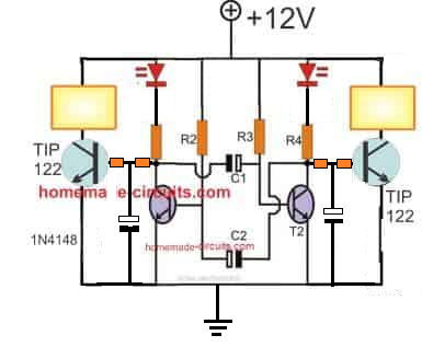
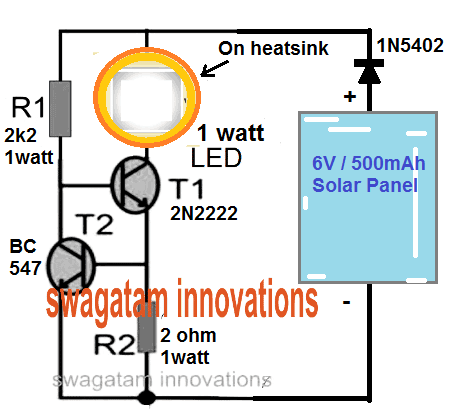
R1, R4 = 680 Ω
R2, R3 = 18K
C1 = 100 μF
C2 = 100 μF
T1, T2 = BC547
For fading effect you can optimize the base resistors and capacitor at the base of TIP122
ok sir thanks. again thanks for the early reply.
Hello sir
Every LED TV technicians badly need a testing device called “LED Back Light Checker” which costs around 1000/- in local markets. if you publish a circuit diagram of this device it will be very useful to them.
Thanks Shanavas, I’ll investigate the concept, and if feasible I’ll create an article on this.
Hello sir,
How can I use 1.0k, 250 MEF capacitor to design a transformerless portable LED light of 12 leds and 230 vac
Hello Thiter, 250uF cannot be used in a transformerless power supply for LEDs
Thanks again
Dear Thivanka, you will need to add separate resistors on each of the 64 LED string. The formula is:
R = Supply DC – Total FWD drop across the 64 LEDs / LED current of the string
use the above formula for all the strings, after that you can join all those strings in parallel
Dear sir,
64 , 5mm leds connected in seris rated 3.2v @20mA (2 strings)
And 64 leds rated 2.8 @ 20mA (3strings)
I need to conect all of this 5 strings.can u pls help me with how to modify or use your ckt to connect these.strings.
OK, understood, you can replace it with a 10uF/400V
Thank you, Glad you liked it.
Are you referring to the 105/400V cap. It is not too big. A 105/400V will produce 50 mA, lower values will produce even lower current, may not be suitable. In the 4rth MOSFET circuit you can add any number of LEDs up to 90 in series, and they all will light up with equal brightness. You just have to adjust the pot accordingly for getting the required brightens.