In this post I have explained the basic working concept of thermal scanners or contactless IR thermometers, and also learn how to make a practical DIY prototype of the unit without Arduino.
In the post COVID-19 era, witnessing doctors holding a contactless temperature gun and pointing toward the forehead of a COVID-19 suspect is a common sight.
The device is actually a contact less thermometer device, which detects the instantaneous temperature of the suspect's body surface and allows the doctor to know whether the person is normal or is suffering from a fever?
Basic Testing Method
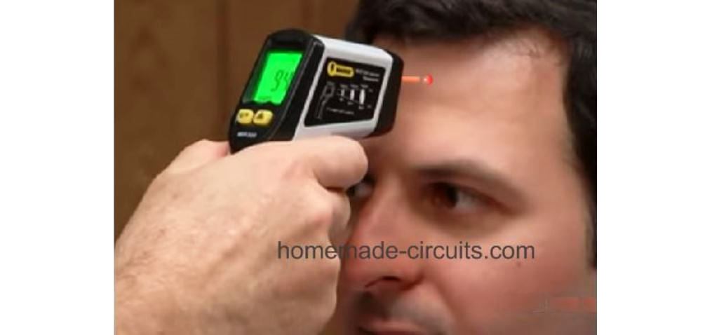
In the testing process, we find the authorized person pointing a laser beam from the contactless temperature gun on the suspect's forehead, and noting the temperature on the device's back LCD panel.
The laser beam actually has no direct connection with the temperature measurement procedure. It is employed merely to help the doctor to ensure that the infrared thermometer is aimed correctly at the ideal place of the body for determining the body temperature mostly accurately.
Stefan–Boltzmann Law
As stated by Stefan–Boltzmann law the total radiant exitance of a body Me(T) is proportional to the fourth power of its temperature, as shown in the following equation
Me(T) = εσT4
In this equation ε signifies the emissivity.
σ denotes the Stefan–Boltzmann constant which is equivalent to the quantity 5.67032 x 10-1212 Wcm-2K-4, where the letter K is the unit of temperature in Kelvin.
The above equation suggests that when the temperature of a body rises, its infrared radiance also increases proportionately. This IR radiance could be measured from a distance without the need of any physical contact. The reading can provide us with the instantaneous temperature level of the body.
Which Sensor is Applicable
The sensor that is best suited, and utilized in contactless thermometers is a thermopile sensor.
A thermopile sensor converts an incident infrared heat map from a distant source into a proportional amount of tiny electrical voltage output.
It works on the principle of thermocouple, in which dissimilar metals are joined in series or parallel to create "hot" and "cold" junctions. When infrared radiant flux from a source falls on the thermopile, it creates a difference in temperature across these junctions, developing an equivalent amount of electricity across the end terminals of the thermocouple.
This electrical output proportional to the heat source can be measured to identify the level of temperature from the body source.
The thermocouple inside a thermopile sensor is embedded over a silicon chip which makes the system extremely sensitive and accurate.
Using the MLX90247 Thermopile Sensor
The IC MLX90247 is an excellent example of a versatile thermopile sensor device which can be ideally used for making a thermal scanner device or a contactless thermometer device.

The IC MLX90247 is made up of piled thermocouple network over the surface of a membrane.
The heat receptive junctions of the thermocouple are strategically positioned near the center of the base membrane, while the differential cold junctions are placed at edge of the device which form the silicon bulk area of the unit.
Since the membrane is designed to be a bad conductor of heat, the detected heat from the source is able to rise quickly near the menbrane center than the bulk edge of the device.
Due to this a quick difference of heat is able to develop across the thermopile junction ends causing an effective electrical potential to develop across these terminals through thermo-electric principle.
The best part of the thermopile sensor is that, unlike standard ICs it does not require an external electrical supply to work, rather it generates its own electrical potential for enabling the required measurement.
You get two variants of the IC MLX90247 as shown below, wherein one variant provides a ground Vss option, and the other is without a Vss pin.
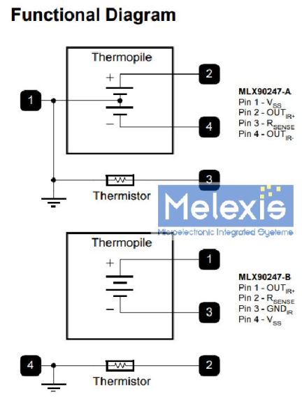
The upper option allows a bipolar measurement of the IR temperature. Meaning the output can show temperatures higher than the ambient temperature and also lower than the ambient temperatures.
The lower option can be used to measure temperature either above the ambient level or below the ambient level, and thus allows a unipolar measurement facility.
Why Thermistor is used in the Thermopile
In the above IC MLX90247, we can see a thermistor being included in the device package. The thermistor plays an important role in creating a reference level output for the external measuring unit stage.
The thermistor is incorporated to detect the ambient temperature or the body temperature of the device. This ambient temperature level becomes the reference level for the output op amp stage.
As long as the IR temperature from the target is below or equal to this reference level, the external op amp amplifier stage does not respond, and its output remains 0 V.
However, as soon as the IR radiance from the body goes past the ambient temperature, the op amp begins responding to produce a valid measurable output which linearly corresponds with the rising thermal output of the body.
Contactless Thermometer Circuit using IC MLX90247 Thermopile Sensor
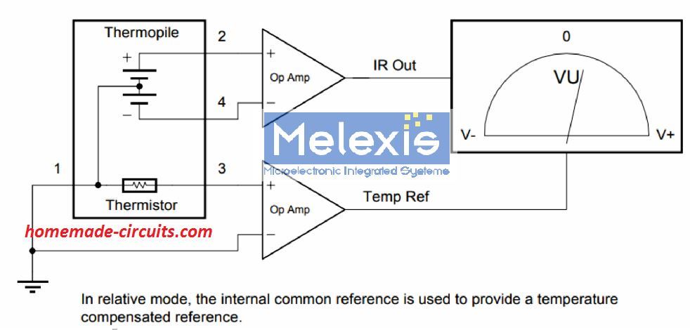
In the above prototype circuit of a contactless IR thermometer circuit, we find the thermopile sensor IC MLX90247 in the bipolar mode, configured with an external op amp designed to amplify tiny electrical from the thermopile into a measurable output.
The upper op amp amplifies the thermocouple output from the IC MLX90247, while the lower op amp amplifies the ambient temperature of the IC.
A simple differential VU meter is attached across the outputs of the two op amps. As long as there no heat emitting body in front of the thermopile, its internal thermocouple temperature remains equal to the adjoining thermistor temperature. Due to this the two op amp outputs generate equal amount of voltages. The VU meter thus indicates a 0 V at the center of its dial.
In case a human body having a higher temperature than the surrounding is brought within the sensing range of the thermopile, its thermocouple output across pin2 and pin4 begins rising exponentially, and exceeds the thermistor output across pin3 and pin1.
This results in the upper op amp generating more positive voltage than the lower op amp. The VU meter responds to this and its needle begins shifting on the right side of the 0V calibration. The reading directly shows the temperature level of the target detected by the thermopile.
Which Op Amp Suits the Application
Since the output from thermopile is supposed to be in microvolts, the op amp to be used for amplifying this extremely small voltage must be highly sensitive and sophisticated, and with very low input offset specification. To satisfy the conditions an instrumentation op amp appears to be the best choice for this application.
Although you may find many good instrumentation amplifiers online, the INA333 Micro-Power (50μA), Zerø-Drift, Rail-to-Rail Out Instrumentation Amplifier appears to be the most appropriate candidate.
There are many great features that makes this IC best suited for amplifying thermocouple voltages into a measurable magnitudes. A basic IC INA333 instrumentation amplifier circuit can be seen below, and this design can be used for amplifying the above explained thermopile circuit.

In this INA333 op amp circuit the resistor RG determines the gain of the circuit, and can be calculated using the formula:
Gain = 1 + 100 / RG
The output result will be in kilo Ohms.
Through this formula we can set the overall gain of the circuit depending on the level of microvolt received from the thermopile.
The gain can be adjusted right from 0 to 10,000 which provides the op amp with an exceptional level of amplifying capability for microvolt inputs.
To be able to use this instrumentation amplifier with out thermopile IC, we will need two of these op amp modules. One will be used for amplifying the thermocouple signal output, and the other will be use for amplifying the thermistor signal output, as shown below;

The set up can be used for making a contactless IR thermometer, which will produce an linearly increasing analogue output in response to a a linearly increasing IR heat, as detected by the thermopile.
The analogue output can be either attached to a milivolt VU meter or a digital mV meter for getting an instant interpretation of the temperature level of the body.
The output Vo could be also estimated through the following equation:
Vo = G(Vin+ - Vin-)
Parts List
The following parts will be needed to build the above explained conctless thermometer circuit:
- Thermopile Sensor IC MLX90247 - 1no
- Instrumentation Op amp INA333 - 2nos
- Voltmeter with a range 0 to 1V FSD - 1no
- 1.2 V AAA Ni-Cd Cells for powering the INA333 - 2nos
The voltmeter reading will need to be calibrated in Celsius, which can be done with some experimentation, and trial and error.
Using a PIR
A normal PIR sensor also works nicely, and provides a cheap alternative for these types of applications.
A PIR includes a pyroelectric material based sensor such as TGS, BaTiO3 and so forth, which goes through a spontaneous polarization when it senses a change in temperature within its detection range.
The polarization charge in a PIR device generated due to change in its temperature is dependent on the irradiation power φe transmitted by the body on the PIR sensor. This causes the PIR output to generated a current Id ωpAd (ΔT).
The device also generates a voltage Vo which may be equal to the product of current Id and the impedance of the device. This can be expressed with the following equation:
Vo = IdRd / √1 + ω2 R2d C2d
This equation can be further streamlined into:
Vo = ωpAdRd (ΔT) / √1 + ω2 R2d C2d
where p indicates the pyroelectric coefficient, ω denotes the radian frequency, and ΔT equals the difference in the detector temperature Td
and ambient temperature Ta .
Now, by applying heat balance equation we find that the value of ΔT can be derived as expressed in the following equation:
ΔT = RT φe / √( 1 + ω2 τ2T )
If we replace this value of ΔT in the previous equation, we get a result that represents the Vo with a bandpass characteristics, as shown below:
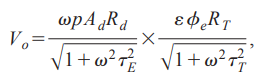
where τE refers to the electrical time constant (Rd Cd), τT indicates the
thermal time constant (RT CT), and φe symbolizes the radiant
power from the target detected by the sensor.
The above discussions and equations prove that the output voltage Vo from a PIR is directly proportional to the radiant power emitted from the source, and thus becomes ideally suitable for contactless temperature measuring applications.
However, we know that a PIR cannot respond to a stationery IR source, and requires the source to be in motion for enabling an readable output.
Since the speed of the movement also affects the output data, we have to make sure that the source moves with a precise speed, an aspect which may be an impossible to implement on a human target.
Therefore, an easy way to counter this it to let the human target be stationery, and replicate its movement by interfacing an artificial motor based chopper with the PIR lens system.
Contactless Thermometer Prototype using PIR
The following paragraphs explain the test set up of a practical thermal scanner system, which can be applied for building a practical prototype, after a thorough optimization of the various involved parameters.
As learned in the previous section, a PIR is designed to detect radiant emission in the form of a rate of change of temperature dT/dt, and hence responds only to an infrared heat which is pulsed with an appropriately calculated frequency.
As per experiments, it is found that the PIR works the best at a pulse frequency of around 8 Hz, which is achieved through a steady chopping of the incoming signal through a servo chopper
Basically, the chopping of the signals allows the PIR sensor to assess and output the body's radiant power as voltage spikes. If the chopper frequency is correctly optimized then the average value of these spikes will be directly proportional to the intensity of the radiant temperature.
The following image shows a typical test set up for creating an optimized measuring unit or the MU.
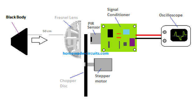
To ensure an efficient working of the system the distance between the IR source and the sensor's field of view (FOV) must be around 40 cm. In other words the radiating body and the PIR lens must be at a distance of 40 cm from each other.
We can also see a chopper system consisting of a small stepper motor with a propeller installed between the fresnel lens and the PIR pyroelectric sensor.
How it Works
The IR radiation from the body passes through the fresnel lens, then it is chopped at 8 Hz frequency by the chopper motor, and the resulting pulsed IR radiation is detected by the PIR sensor.
The output AC equivalent to this detected IR is then applied to the "signal conditioner' stage made with many op amp stages.
The final amplified and conditioned output from the signal conditioner is analyzed on an oscilloscope to check circuit's response to a varying radiant exitance of a body.
Optimizing the PIR and the Chopper
To get the best possible results, the following criteria must be ensured for the PIR and the chopper association.
The chopper disc or the blades should be positioned to rotate between the fresnel lens and the PIR internal sensor.
The fresnel lens diameter should not be more than 10 mm.
The focal length of the lens should be around 20 mm.
Considering the fact that the typical sensing area of Ad 1.6 mm φ and is installed close to the focal length of the lens, the field of view or FOV is found to be 4.58 o using the following formula:
FOV(half angle) ≈ |tan-1 [(ds / 2) / f]| = 2.29 o
In this equation ds denotes the detectable diameter of the sensor, and f is the focal length of the lens.
Chopper Blade Specifications
The working efficiency of the contactless thermometer largely depends on how the incident infrared is pulsed through the chopper system and
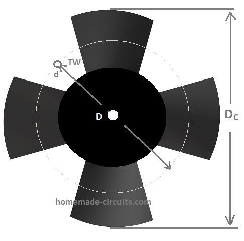
In this chopper the following dimensions must be employed:
The chopper should have 4 blades and a diameter Dc should be around 80 mm. It should be driven through a stepper motor or a PWM controlled circuit.
The approximate rotational frequency should eb around 5 Hz to 8 Hz for optimal performance.
The PIR fresnel lens must be positioned 16 mm behind the pyroelectric sensor, such that the incoming IR signal diameter falling on the lens is around 4 mm, and this diameter is supposed to be much smaller than the "tooth-width" TW of the chopper disk.
Conclusion
A contactless thermal scanner or an IR thermometer is a very useful device which allows measuring human body temperature from a distance without any physical contact.
The heart of this device is an infrared sensor which detects the level of heat in the form of radiant flux of a body and converts it into an equivalent level of electrical potential.
The two types of sensors which can be used for this purpose are the thermopile sensor, and the pyroelectric sensor.
Although physically they both appear similar, there's a huge difference in the working principle.
A thermopile works with the basic principle of a thermocouple and generates an electrical potential proportional to the difference of temperature across its thermocouple junctions.
A pyroelectric sensor which are normally used in PIR sensors, operate by detecting the change in temperature of a body when the body with a higher temperature than the ambient temperature crosses the field of view of the sensor. This change of temperature level is converted a proportional amount of electrical potential at its output
Thermopile being a linear device is much easier to configure and implement into all forms of thermal scanning applications.
References:
Instrumentation amplifierThermopile sensor melexis
Infrared Thermometer
Comments
Hallo again Mr.Svagatam.
Think you for Your keep good doing – the site – despite “winds of close to WW3 time”/
Only nowdays 06sept2023 I pay my attantion to details of the cirquit – by datasheet the MLX90247 pins 1 and 3 are termopile’s exit with pins 2 and 4 are thermistor’s exit – turn around from Your picture.
INA333 hardly can work good stabile with 2 only 1.2V NiCd power supply – is necessary at least 3.5V.
You gave very detailed set of equations for developers of a scientifical equipments, but not notify it for readers and just forget to describe a wery important to all users phisical phenomena – EMITANCE.
An EMITANCE is a property of any heated surface, to know the surface’s EMITTANCE level iswery important to correct measure of temperature by all contactless thermometers, for example – a kettle of fresh-bioled water (99,9 Cendegree by a submersible thermometer – danger of burns) will be at IR-contactless thermometer these temperatures: if the kettle produced of any plastic – will be around 95-99 Cendegree, if the kettle produced of outer surface enemaled steel is 99,8 Cendegrre if the kettle produced of a keramik-teracota depends on enemal of outer surface will be 99.6-85 Cendegree but if the kellle produced of any polished like a mirror outer surface steel -it will be 45-50 Cendegree only – all kinds of kettles are fresh boiled!!!!! All IR contactless thermometers are set up to EMITTANCE 98% – same 0.98 if there are not the EMITTANCE set up, or has the button(s) to select or set up the surface’s emittance level. It is essential to all IR-based feedback-controls correct work and to avoid of home-fires burns of skin and of other similar hard problems.
Please change the Your article if You think the comment is correct, Sir. Sincerely. Good luck You.
Thank you so much Igor,
I greatly appreciate your valuable information.
I think you have provide a lot of information about emittance and the readers will find your comment very useful and read it thoroughly.
Hi, With reference to your article “Home » Infrared (IR) » How Contactless Infrared Thermometers Work – How to Make One”. It was an excellent and very informative article, and I have now made one (The thermopile version). Thank you
Thank you, Glad you liked it!
Long live Mr Swagatam for people’s better live… ????????????????????????????????????
Thank you Gk!