• Skip to main content
  • Skip to primary sidebar

Homemade Circuit Projects

Need circuit help? Post them in the comments! I've answered over 50,000!

Blog | Categories | About | Hire Me | Contact | Calculators-online
You are here: Home / Energy from Magnets and Earth / How to Generate Electricity Using a Flywheel

How to Generate Electricity Using a Flywheel

Last Updated on May 20, 2026 by Swagatam 122 Comments

In this article we investigate the flywheel concept and learn how it may be used for charging batteries and also enhance to work at the overunity level.

Table of Contents
  • What is a Flywheel
  • Typical applications of a flywheel incorporate:
  • Using Flywheel for Generating Free Electricity
    • The Flywheel Circuit Setup
  • How it Works (Overunity)
    • Feedback from Mr. Mark Baiamonte
    • Solving the Query
      • Finalized Flywheel Design By Mark
      • A Few Optimization Tips from Mr. Thamal Indika

What is a Flywheel

According to Wikipedia, A flywheel is a spinning mechanized machine utilized to stock and release rotational power.

Flywheels are seen to possess an inertia, termed the "moment of inertia" which therefore resists alterations in rotational to their speeds, much like the mass (inertia) of an automotive system prevents its acceleration.

The level of power trapped in a flywheel is proportional to the square of its rotational movement.

Energy is delivered to a flywheel by the utilization of a torsional power to it, consequently raising its rotational velocity, and as a result its accumulated power. On the other hand, a flywheel produces collected energy by making use of torsional power to a physical load, consequently lowering the flywheel's rotational rate.

Typical applications of a flywheel incorporate:

Offering nonstop energy where the source of energy is discontinuous. As an illustration, flywheels are utilized in reciprocating motors since the power source, torque from these motors, are irregular.

Dispensing energy at rates beyond the capability of a persisting source of energy.

This is often accomplished by gathering energy in the flywheel progressively then simply discharging the energy swiftly, at rates that surpass the capabilities of the source of energy.

Managing the alignment of a mechanised equipment. In this kind of usages, the angular speed of a flywheel is specifically routed as a torsional power to the connecting mechanized system while energy is moved to or from the flywheel, consequently provoking the connecting equipment to move into certain expected position.

Flywheels are ideally made from steel and move over special high grade bearings; these are typically confined to a revolution value of several thousand RPM.

A number of contemporary flywheels are constructed of carbon fiber components and implement magnetic bearings, making it possible for these to rotate at rates up to 60,000 RPM.

The above discussion clearly states that flywheels have the potentials to generate an output power that may much higher than the input once it has been rotated to some specified high speed.

From the above discussion we can conclude that using a flywheel an overunity electricity generator can be achieved without much complications and skepticism.

Considering Flywheel as an Effective Free Electricity Generator

In a one of my earlier posts I have discussed a similar concept using a pendulum and have tried to convey the method of using it for achieving overunity limits.

In this article we'll see how a flywheel can be used for executing an overunity result, and derive over 300% more output than the applied input.

In the diagram below we can see a simple flywheel with a motor set up:
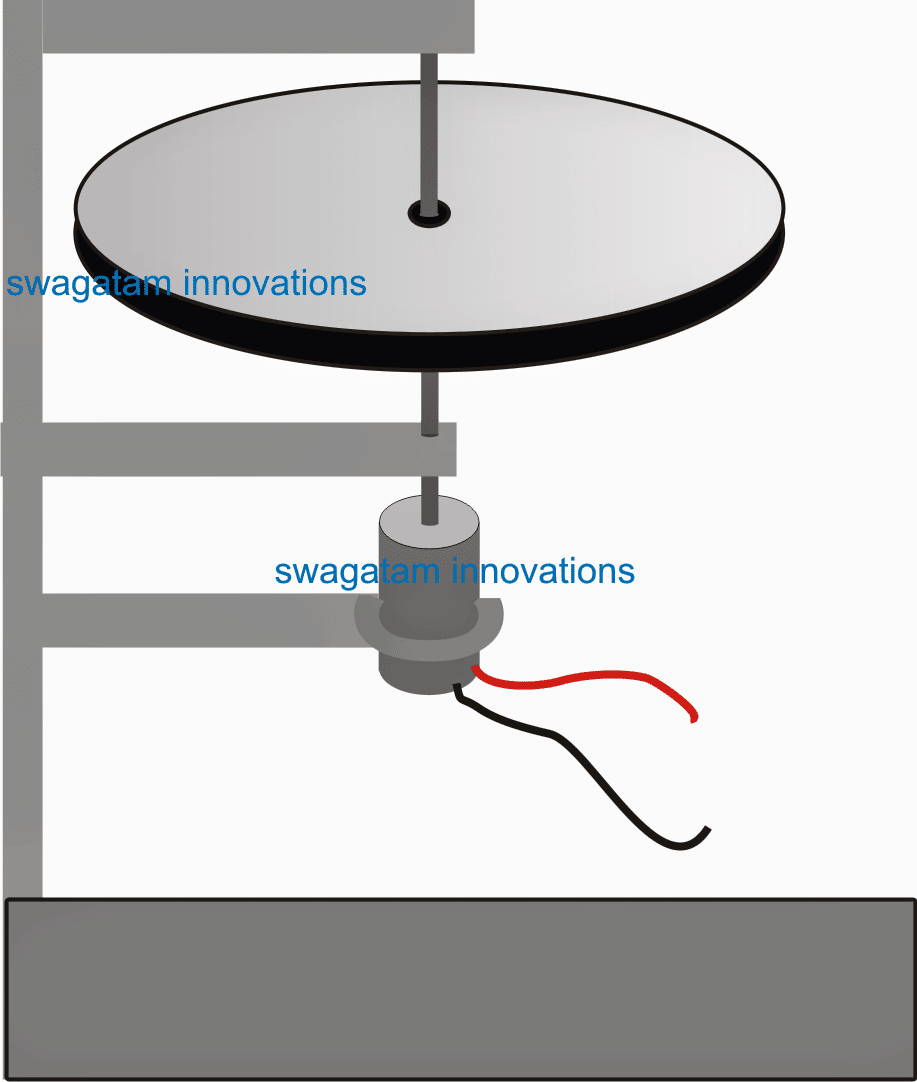
This can be seen as a manual electricity generator using a flywheel wherein the flywheel needs to be pushed occasionally for sustaining a consistent rotation over the attached motor.

The motor wires can be appropriately terminated with a battery for acquiring the proposed free electricity from the set up.

The advantage of this set up is that once the flywheel is rotated with the specified maximum torque, the rotational can be sustained by pushing the flywheel with significantly less amount of energy.

Although efficient, the above set up may not look too impressive due to the requirement of an individual all the time near the system.

Using Flywheel for Generating Free Electricity

In the above sections I have explained regarding how a flywheel can be used for generating excess electricity from its stored potential energy when it's given a swift spin using an external torsional force. In the following discussions we'll learn how the system can be made into a perpetual motion without the need of any external intervention.

In our last discussion we understood the naturally attributed overunity feature of a flywheel, and learned how it can be used like an efficient machine for generating free electricity with the help of a frequently applied external minimal sustaining force to it.

However, in order to transform the flywheel into a  free electricity generator andalmost perpetual, and automatic without the requirement of any manual intervention, the following shown smart idea can be incorporated.

The Flywheel Circuit Setup
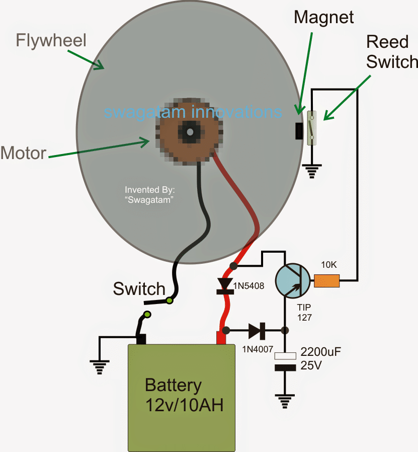
If the explanation provided in Wikipedia is believed to be correct, then the above design should work as per the proposed overunity concept here.

In the design above we can see an appropriately calculated flywheel, motor, and a battery circuit set up.

How it Works (Overunity)

The figure shows the top view of the flywheel, the attached motor being right under the flywheel, shown in a pixelated form.

The motor wires are connected to a battery which needs to be charged, via a blocking rectifier diode (1N5408). This diode makes sure that the voltage from the battery remains blocked while the energy from the motor is allowed to reach the battery.

A PNP transistor network can also be witnessed, whose base is configured with a reed switch.

The reed switch is supposed to be activated through an embedded magnet sealed at the edge of the flywheel.

Initially the switch connected in series with the negative wire is kept toggled off, and the flywheel is given is tight rotational spin (torque) manually or with any desired external means.

A soon as this is executed, the switch is immediately toggled ON.

Here the flywheel dimension is assumed to be significantly large such that the "switch ON" action (battery connected) inflicts only a minor resistance to the torque of the flywheel.

Once the above action is initiated, the motor instantly begins generating and supplying electricity to the battery.

Also in the course of its rotational cycle, the magnet attached with the flywheel edge begins switching the corresponding reed switch intermittently.

The reed switch in turn switches the PNP transistor at the same rate creating momentary short across the 1N5408 diode so that during these instants the battery power is reverted to the motor for applying back the required sustaining torque to it.

The 2200 uF capacitor further aids to this and reduces the load on the battery each time the transistor switches ON.

Now since the reed switch is toggled only for a fraction of time of each complete rotation from the flywheel, except for these periods, the rest of the rotational length of period is used for generating free extra electricity for the battery.

It implies that while the flywheel is rotating only a fractional energy from the battery is used for sustaining its optimal torque, while a significantly large amount of its energy is transferred to the motor for generating an equivalent amount of charging current for the battery.

The above explained scenario ensures a perfect self-sustaining flywheel system which becomes capable of generating free electricity in excess tow hat is being used as its sustaining input.

The shown 2200 uF capacitor may be increased to some higher value and if possible super capacitors can be tried for further enhancing the efficiency of the system.

Feedback from Mr. Mark Baiamonte

Can you use a 3 phase washing machine motor and how would it be wired? I have been fooling atound with a windmill and got it to work but not enough wind. You plans are excellent and i would love to try it. Here is my motor.

Solving the Query

A 3 phase motor could be difficult and confusing to wire with the shown flywheel circuit, because the motor would need a 3 phase to single phase DC conversion and a DC to 3 phase reception from the transistor...

Finalized Flywheel Design By Mark

I built the flywheel and it works! I only had a 2200uf 16volt. I used a motor from a treadmill.

What the biggest size capacitor i could use? Thank you very much. This is the first thing i made like this. I enjoyed it very much.

Only sorry i didn't start fooling around with this kind of stuff at a younger age. Thank you again for your design and your time.

Mark Baiamonte Ashley,

Pa USA

[email protected]

My Response

That's great Mark, thanks for updating the info.

The capacitor value is not critical, however bigger values might help to increase the efficiency of the system, so you could try adding a a couple of more 2200uF in parallel.

Best Regards
Swag

A Few Optimization Tips from Mr. Thamal Indika

I saw a big difference by attaching a 4700uf capacitor to the motor terminals and the speed of the fly wheel increased significantly. At the same time i checked the out put of the motor and it is about 6.5 V . I am going to  rotate another motor by that output current and using that separate motor i can create a good generator by moving magnets on a fixed coil.

I hope to use super magnets like N38 (Diameter 2CM, Width 1CM) and use guage 20 coils . I can make an assembly for that and i will attach another fly wheel to the shaft attached to that separate  motor so that the speed will be increased.  . Then it will generate more that 12 V current and about 2 A. Also i can change the amount of ampere by attaching more coils . Then i can give that out put current to the 7.4 V 1A Dialog Router battery and it will charge well.

I think this is a good modification to your circuit design and instead of giving the output current of the battery  through a rectifier , i am going to rotate another separate motor by that current and thus running a generator and supply the output of the generator to the battery. please note at present i use a 7.4V 2A Dialog Router with a 6V cassette motor for your design and the speed of the fly wheel increased significantly by attaching a 4700uf capacitor to the terminals of the 6V cassette motor .

It brought some successful results. I just checked the charger of this battery and it is 12V 1A charger .   I hope i will be able to create a generator that would provide 12V 1A.

You'll also like:

  • electricityfrommotorCellphone Charger Circuit Using Pendulum Generator
  • freeenergybicyclegeneratorBicycle Generator Circuit
  • THE HIGGINS ENGINE: Generating Electricity from Gravity
  • Build this Unidirectional Wind Turbine: Wells Turbine

Filed Under: Energy from Magnets and Earth Tagged With: Electricity, Flywheel, Free, Generate

About Swagatam

I am an electronics engineer and doing practical hands-on work from more than 15 years now. Building real circuits, testing them and also making PCB layouts by myself. I really love doing all these things like inventing something new, designing electronics and also helping other people like hobby guys who want to make their own cool circuits at home.

And that is the main reason why I started this website homemade-circuits.com, to share different types of circuit ideas..

If you are having any kind of doubt or question related to circuits then just write down your question in the comment box below, I am like always checking, so I guarantee I will reply you for sure!


Previous Post: « Remote Controlled ATS Circuit – Wireless Grid/Generator Changeover
Next Post: Transformerless Voltage Stabilizer Circuit »

Reader Interactions

Questions & Answers

Total Posts: 122
Newest Oldest
Carl Monto
November 28, 2025 • 9 months ago #192573

I am very interested in electric generator.
Please tell me the phone number and what state it is in or country.

Reply
Sudi Mteza
June 27, 2025 • 1 year ago #182958

Altonetor RPM 1500, 3PHASE, 18.75KW. Motor 2800 RPM single phase.
I need help on size of pulley in motor, flywel and altonetor also flyweel kg.

Reply
SwagatamAdmin
June 27, 2025 • 1 year ago #182974

Hey Sudi, Here’s the calculations for you:
Motor RPM × Motor Pulley Diameter = Alternator RPM × Alternator Pulley Diameter

Given:
Motor RPM = 2800
Alternator RPM = 1500
Let us assume motor pulley = 100 mm, then:
2800 × 100 = 1500 × Alternator pulley
Alternator pulley = (2800 × 100) / 1500 = 186.66 mm
So Ideal Pulley Sizes:
Motor pulley: 100 mm
Alternator pulley: 190 mm approx…(you can also use 90 mm and 170 mm, or any set that keeps ratio 1.86:1)

Flywheel Size and Weight (Rough Idea):
For a 18.75 kW alternator at 1500 RPM, we can keep:
Flywheel diameter: around 500 mm to 700 mm
Weight: around 60 kg to 100 kg
Material: Cast iron or steel
Too heavy flywheel may overload motor at startup. So better to try with 60–70 kg first, if motor can handle, then try more.

Reply
SİNAN ÖZYOLDAŞ
January 3, 2025 • 2 years ago #167704

Since 16 years, I have been dealing with angular energy electricity generation systems (R&D). My positive designs about angular continue. In this regard, my own financial means are insufficient, I had meetings with many businessmen, they accepted the financing of the project, but they gave up when it came to signing a protocol, that is, when it came to formalisation. If there is an entrepreneur who will take firm steps with me on this path, who is idealistic, has financial means and wants to make an official protocol, I would like to meet. 98% of the published videos are wrong and do not work. I know the mistake they all make.

Reply
Ayanokoji
April 12, 2024 • 2 years ago #151538

How can I bring the electricity generated out?

Reply
hello.there
January 10, 2024 • 3 years ago #148494

how fast will the battery recharge itself?

im guessing you can use this to top up a low battery too? basically a dead battery charger?

Reply
SwagatamAdmin
January 10, 2024 • 3 years ago #148496

It will depend on the flywheel size.
Yes it can be used for keeping a battery topped up, but might not be suitable for dead batteries.

Reply
Macaulay
June 24, 2023 • 3 years ago #143647

Can I use this to operate two 1.5hp borehole pumps on the farm. Thanks

Reply
King post
March 10, 2023 • 3 years ago #140916

Sir, can you extract power from this device to power another device when this particular device is running

Reply
SwagatamAdmin
March 10, 2023 • 3 years ago #140921

I don;t think that’s possible.

Reply
Sylvester
January 5, 2023 • 4 years ago #138596

what if i integrate a car alternator to constantly charge the battery, in place of a diode rectifier, connected through a belt and pulley attachment to the flywheel shaft, would that be fine ?

Reply
Kim Jensen
October 31, 2022 • 4 years ago #134225

Hello,
Does it matter if the flywheel is vertical or horizontal placed for the operation to be optimal ?

Best Regards,
Kim Jensen

Reply
SwagatamAdmin
October 31, 2022 • 4 years ago #134226

Hello, I don’t think it really matters whether the flywheel is held vertically or horizontally.

Reply
Ali
September 18, 2022 • 4 years ago #133334

Dear Sir Swagatam
Hello. You have probably seen many fake videos about free electricity production on the Internet. I will send you a video in this case to your Email address that a friend has sent me and I hope this one is real . Those fake videos remind me of the story of a man sitting by the sea with a bowl of yogurt and pouring spoonfuls of yogurt into the water and stirring it with the spoon. A passerby asked him: “what are you doing”? The man replied: “I am producing yogurt”. The passerby said: “but you cannot turn the sea water into yogurt with a bowl of yogurt”, and he answered:” I know, but imagine how much yogurt I will own/have if the sea water turns into yogurt”.
Waiting for your hopeful answer, I remain
with best wishes
Ali

Reply
SwagatamAdmin
September 18, 2022 • 4 years ago #133339

Thank you Dear Ali,
I saw the video which you sent me. Unfortunately it is also one of those fake videos from youtube, and the results are impossible to achieve through the shown setup.

Reply
Ali
September 18, 2022 • 4 years ago #133346

Dear Sir Swagatam
Hello. Thank you so very much for answering me. Please apologize for taking your precious time.
He who never forgets your kindness
Affectionately yours
Ali

Reply
SwagatamAdmin
September 18, 2022 • 4 years ago #133350

No problem Ali, You are most welcome!

Reply
Emejakpor Emmanuel
July 19, 2022 • 4 years ago #131708

Good day sir. I read the explanation and you said that the motor will produce Power to the battery. I quote “Once the above action is initiated, the motor instantly begins generating and supplying electricity to the battery”. How is it possible that a DC motor will generate dc voltage or is it a special motor that will act as DC gen and dc motor? From your diagram, the transistor and reed switch function is to enable the motor to get supply from battery to motor. Please sir explain

Reply
SwagatamAdmin
July 19, 2022 • 4 years ago #131711

Hi Emmanuel,
When a DC motor shaft is rotated by an external force the motor starts generating electricity, that’s a standard working principle of all DC motors.

Yes that’s right the transistor and reed switch function is to enable the motor to get supply from battery to motor.

Reply
Rick
June 20, 2022 • 4 years ago #128081

I have started building my own flywheel to generate electricity to be stored for use.im waiting on the mail to bring me the rest of what I need,wish me luck!

Reply
SwagatamAdmin
June 20, 2022 • 4 years ago #128082

Sounds great! I wish you all the best with the project!

Reply
Mehrdad
July 31, 2021 • 5 years ago #92858

Sir engineer Swagatam
Hello. A friend of mine has recently sent a video regarding generating electricity using magnetic field. I sent it to your Email to please check out and tell me weather it is real and if so, would you do a favor and introduce it as a project in your site along with technical features of it such as type of magnet, size and diameter of screw and so on?
Thank you in advance
Wish you all the best
Mehrdad

Reply
SwagatamAdmin
August 1, 2021 • 5 years ago #92904

Hello Mehrdad,

that is a 100% fake video and will never work. There are many such videos on youtube created to fool the audience, so please do not build them.

Reply
Mehrdad
August 1, 2021 • 5 years ago #92918

Sir engineer Swagatam
Hello. I thank you very much for your reply.
Wish you all the best
Mehrdad

Reply
SwagatamAdmin
August 1, 2021 • 5 years ago #92922

You are welcome Mehrdad!

Reply
John Davies
July 30, 2021 • 5 years ago #92835

I wish you guys would stop wasting your time, you are NEVER going to get more energy out of a system than you can put in, the law of conservation of energy has stood the test of time for centuries for good reason.
Consider this, you start with a flat battery and spin it up by hand, the battery will never charge and the flywheel will lose momentum and stop.
All this system does is maintain the speed of the flywheel while slowly depleting a charged battery.

Reply
scott burrell
October 24, 2021 • 5 years ago #102438

Your comment about Flywheel energy . Yes its true about Law of Conservation however what about Pulsed motors and Flywheel Generators producing 1 amp of pulse into the battery.
In light of super capacitors coming online. What I”m saying is … can you not produce energy slightly
faster than your dispersing it. That is to save on specific amperage or milliamperage loads say for example
a household air conditioner. It eats like 16 amps to operate but if you could differ most of that lost energy
you energy bill would sure come down.
thank you

Reply
John Davies
November 2, 2021 • 5 years ago #103535

“Your comment about Flywheel energy . Yes its true about Law of Conservation however what about”…..
No.

Reply
Yusuf
February 2, 2021 • 6 years ago #86626

Hello sir.i would need to try this concept with high power motor and generator,around 1500w-2500w.its looks practical I mean.i have a certain suggestion since I deal with car alternator works.any generator spins at certain speed to produce power.according to me ,this rotation is essential for the stator coils to experience changing flux.hop it’s clear.i want to design a generator which does not require spinning power but I will use an oscillator driver to control the magnet polarity inside the stator coil,, through the field excitation coil like car alternators do. about 50hz to 100hz frequency.though stationary,the stator coils will still experience changing flux as of moving generator.think of a inverter transformer….is that practical sir..please reply sir

Reply
Raja
October 20, 2023 • 3 years ago #146365

Yusuf…. Seems you are correct. What’s the status right now?

Reply
SwagatamAdmin
February 3, 2021 • 6 years ago #86649

Sorry Yusuf, I have no idea about the details and the questions that you have asked, since my expertise is with the electronic circuits only.

Reply
Sean Frederick Parducho
November 22, 2020 • 6 years ago #84743

Can anything from the Earth’s Rotation affect the energy stored in a Flywheel? If this is in the text already, I am sorry and I might have just passed that part. I really need this for my project.

Reply
StefCo
October 24, 2024 • 2 years ago #164156

The Earth is not spinning. It is stationary and closed with firmament. Under the firmament rotate the Sun and the Moon.

Reply
SwagatamAdmin
November 23, 2020 • 6 years ago #84757

Sorry, I have no idea about it!

Reply
alex
March 9, 2020 • 6 years ago #77168

hello friend,,
i have tried build this mechanism ,as the followoi circuit explained above,
the stuff i have are
6v rechargable battery,
3v small dc motor ,
the electronic component i use are same as your circuit,
But , its still stop ,lost power after about 3hours,
is it may be because the batterey and the motor i use are to small?
..

Reply
SwagatamAdmin
March 9, 2020 • 6 years ago #77171

Hello Alex, the motor and battery specs must match, a 3V motor cannot be used to charge a 6 V battery.

Reply
alex
March 9, 2020 • 6 years ago #77177

i have tried to change the battery with 3v,but its not strong enough to rev the motor at high rpm,,
can i change the others parts,
the transistor,or diode maybe ,so its can run with both just 3v motor and battery??

Reply
SwagatamAdmin
March 9, 2020 • 6 years ago #77178

Please try heavier flywheel, 6V motor and 6V battery. the motor amp output must be at least 7 time less than the Ah.
other parts does not need to be changed

Reply
alex
March 12, 2020 • 6 years ago #77228

hello brother Swagatam,
i have change 3v motor with 12v,
and i am using four 3.7v rechargable li ion battery,each 6800mAH,
so,is it right that for 6800mAH it is need at least 1.2Ampere current rate to charger the battery?
,but ,i dont realy know ,how much current generate by my 12v motor..
,maybe its preety to small,
and ,how i can boost the output ampere from my 12v motor?
or,do i need to change with 12v motor with higher rate Ampere?
thank you..

Reply
alek
March 23, 2020 • 6 years ago #77411

hello Bro,
more and more iam investigate about this prjoect,
i found that,
its need more calculations ,i found a relations between RPM-reed switching-Charging period- magnetic field afected by the RPM too,
,Mean,with high RPM ,which is need to make the motor generate strong enough electricity to charge the battery,,,the high RPM causes in ‘need some calculations to control the time/period of reed switching,
seems,..i need add another method to replace the reedswitch,to ensure the charge period keep.bigger no matter how high RPM its rotate,

Reply
SwagatamAdmin
March 23, 2020 • 6 years ago #77417

No issues bro, I appreciate your dedication, keep up the good work…you can add a Hall sensor instead

Reply
alek
March 16, 2020 • 6 years ago #77297

based on trial i have done,
which is in small size,
use only 3×1.2volt battery,
small flywheel ,65mm diameter,
,i assume that,its will work better with larger scale,
,12volt 3ampere DC motor,
,12 volt 5Ah battery,
,and absolutly,bigger and heavier flywheel,
,multiplying that 65mm,so its good to use about 650mm flywheel,
the flywheel sure,its the key ,the heart of this system,
and based on my trial, the shape of the flywheel are the most critical factor instead of the weight
mean,
with the same weight but bigger diameter,and less thick,and consentratting its mass weight pn its radian, ,mean, the flywheel has a less weight near its center

Reply
SwagatamAdmin
March 16, 2020 • 6 years ago #77299

Thank you for your valuable research, hope this info will help the other readers to optimize the system better!

Reply
alex
March 16, 2020 • 6 years ago #77296

hello bro,
sorry for just reply now,..
i’ve done some modifitcation of thr circuit,
first i change motor with nee 12volt with output current about 150mAh,depend on rpm its rotate, then i use 3battery with lower Ampere/hours,
i found a 1.2volt baterry with just 700mAh,mean its need only 140mAh current to charge,,1,,use 3battery,
and i do modification on electronic too,
i use only diode,and reedswitch,
and my last trial,i can run this overunity 8hours with no drop rpm,
until my reed switch damage,,
i need better long life reed switch,
but,overall,
its work bro,
mean,there are big posibilty for us,to build a small to.medium scalle of what peoples around the world search,develop,
a free electricity
,i will keep going on on this project,
,

Reply
SwagatamAdmin
March 16, 2020 • 6 years ago #77298

That’s great bro, appreciate your efforts!

Reply
SwagatamAdmin
March 12, 2020 • 6 years ago #77235

Hello Alex, I can’t suggest accurately without seeing your circuit practically, may be you can try the following concept instead to get improved results:

https://www.homemade-circuits.com/how-to-recharge-discarded-lead-acid/

Reply
alex
March 9, 2020 • 6 years ago #77182

ok…bother…
i will change my motor,
about flywheel,
i think its already too heavy,
for 3v motor,
i made flywheel with 45mm diameter, and 8mm thickness,
,,
its slow at start with using 3v motor and battery,
need several second to rev high,

Reply
alek
March 17, 2020 • 6 years ago #77313

good nite bro,..
its 00.30 am in my country,haha,
,i wish i can send you a video of my experiment,
would like to give me your Whatsaap maybe?
now iam running this device bro
i have made a simple reed switch,to replace the damaged one,,,
its about…,3hours ,and rpm are stabil,
hope its will keep run till tomorow
,

Reply
SwagatamAdmin
March 17, 2020 • 6 years ago #77320

Thanks alek, I hope you will succeed with the project! Sorry, i discuss through comments only in this website, wattaspp is not possible.

Reply
alek
March 16, 2020 • 6 years ago #77302

one more ..
aftet that 8hours,,
it was stoped because the reed swicth was damaged,i dont know why,,i let it running while i was sleep ,
maybe because i use the most cheap one so its weak,,
but,,,over that,,,my 3battery are remind have a power,
mean,if the reed switch was not damaged,the sytem still running,

Reply
SwagatamAdmin
March 16, 2020 • 6 years ago #77307

You can replace the reed relay with a Hall effect device which will never get damaged due to high speed or frequency

Reply
alek
March 16, 2020 • 6 years ago #77301

thank you Brother,
I keep going on to do this project,
first ,build the small scale with 100% work,,,
,pocket size,,so people can use this to charge their gadget,cellphone,laptop,etc even when no comercial electricity avaiable
,i think its good enough if the battery as power source can keep running for few months,,,4-5-6 or,
1 year, ,with 3-4hours daily use ,,4times/ day maybe,,,
,,

Reply
SwagatamAdmin
March 16, 2020 • 6 years ago #77306

No problem bro, I wish you all the best!

Reply
alex
March 9, 2020 • 6 years ago #77186

Well,thank you brother for replay me …
i planning to add some piezo element instead of coil and magnet or athers motor infront of the motor and flywheel ,and some mechanic attached so the flywheel hit piezo element and generate electricity,
in my test ,piezo need very little forces to generate electricity,
and i hope it will increase efisiency of this system,
electricity generates by piezo,,i will draw it to recharge the battery too,
and,because i add more than one piezo,the others i will use to charge another battery so i can use this battery to power any othets electric device,
can you suggesst me,
a circuit which to make the electricity from piezo is can charge the battery?

Reply
SwagatamAdmin
March 10, 2020 • 6 years ago #77195

No problem Alex, the current from a piezo will be negligibly small to charge any form of battery.

Reply
SwagatamAdmin
March 9, 2020 • 6 years ago #77185

OK, but the flywheel needs to be moved with hand initially at full speed, only then it may start producing the intended results.

Reply
alex
March 9, 2020 • 6 years ago #77176

ok …thankyou brother…
i will replace my motor ,
,,

Reply
Bk
January 20, 2020 • 7 years ago #75114

Hi.where can i find a diagram with specific specs for this

Reply
Darediamond
November 15, 2019 • 7 years ago #72077

The only problem to make this concept work on large scale is LENZ. By large scale, I mean placing coils on a stator and using the flywheel effective concept to rotate magnet over the coils. So the solution is to wind coils of equal length of wire, connect the coils in clockwise counter-clockwise fashion and then make the Mandy dc oriented by placing one part all North pointing out and other side all South pointing out. Thereafter close the magnetic open field of individual magnet with metal plates on the back of the rotor which is also acting as flywhrel.
I wish I can add pictures to this comment for everyone to understand what I saying in words here.

Reply
SwagatamAdmin
November 15, 2019 • 7 years ago #72085

Appreciate your feedback Dare, you can send the pics to my email, I’ll post them under your comment.

Reply
lili
October 30, 2019 • 7 years ago #71516

hello sir ,
I need to know (How to generate electricity for free using a magnetic energy and Flywheel to light a bulb

Reply
Ravindra
August 13, 2019 • 7 years ago #69224

Hellow sir, highly appreciate your quick reply. Nearly 60v is required to run the motor at maximum rpm.And on the other hand output current becomes 3-4A at 12v only if rpm is nearly 2000. So with nearly 50v and nearly 0.3A charging a 12v battery isn’t possible? Anyway I will try with the setup. Is the circuit ok for higher voltages.
Thanks

Reply
SwagatamAdmin
August 13, 2019 • 7 years ago #69227

Thank you Ravindra, as far as I understand using intermediate converters will not work for this application. If the motor is 60V then the battery will also need to be 60V rated.

Wish you all the best!

You can also refer to this Bedini charger, having similar set up

https://www.homemade-circuits.com/how-to-recharge-discarded-lead-acid/

Reply
kintu shaami
December 21, 2020 • 6 years ago #85523

Thanks for your Contribution to Flywheel energy, my question is can a treadmill motor be helpful in this Flywheel energy?

Reply
SwagatamAdmin
December 22, 2020 • 6 years ago #85546

Thanks, If it is a permanent magnet type motor, then maybe it can be tried

Reply
kintu shaami
December 24, 2020 • 6 years ago #85580

Thanks your reply, yes it is, but I have no idea with whole Concept if you can enlighten me the basics I appreciate

Reply
Ravindra
August 13, 2019 • 7 years ago #69220

Hellow sir, thanks for your early reply.my Devo motor is brushed and a DC motor.and works as a regular DC motor with rpm of 3000. Input needs to be given with a step up circuit (I am having one 10v to 30v input & 12v to 60v output) when it works as a DC generator step down circuit has to be used.(I am having that too.10A 5v to 60v input and 12v output) is it possible to modify the circuit.
Thanks

Reply
SwagatamAdmin
August 13, 2019 • 7 years ago #69223

Hello Ravindra, then you can try it. Connect it directly with the shown circuit without any converters. Converters may reduce the overall efficiency.

You can also try the concepts presented in the following article:

https://www.homemade-circuits.com/making-a-self-powered-generator/

Reply
Ravindra Jayathilake
August 12, 2019 • 7 years ago #69201

hellow Sir,
kindly instruct me, I am having a 72v 110w servo motor and hope to experiment with flywheel energy following your circuit. kindly let me know if it is possible with the motor and step up and down circuits and a 12v battery. If yes ! what are the changes that should be done to the existing circuit. And the way to calculate the flywheel. Thanks for your instructions in advance.

Reply
SwagatamAdmin
August 13, 2019 • 7 years ago #69218

Hello Ravindra, I am not sure whether a servo motor will work or not. According to me it should be a regular brushed DC motor.

Reply
K.K. Thamal Indika
September 7, 2018 • 8 years ago #62862

Dear Swagatam Sir, I could not send you a message for very long time. Actually i was able to create a rotor with 8 magnets and using my A3144 Magnet sensor hall effect circuit i was able to see a good rotation with much speed . i used two electromagnetic coils to drive the rotor and my work has been successful. This weekend i am winding some generator coils and there will be 7 generator coils and i will fix them to the stator of my Electromagetic Generator. I hope i can charge my 7.4 V 2A Dialog Router Batter y well using my Electromagnetic Generator and the current for driving my rotor is also taken by this battery. I hope i can run my generator for many days without and voltage drop of the battery. Because it is being charged by my 7 generator coils . I am going to give the out put current to the battery through a LM 317 Regulator circuit and i just need to make my generator self running by attaching more generator coils and directing the output current to the magnet sensor hall effect circuits as done by the “Bill Muller Self Running Over Unity Device” I will inform you about my work . These Days i am much happy as my rotor is running very smoothly with a reasonable high speed. Best of luck to you .

Reply
SwagatamAdmin
September 7, 2018 • 8 years ago #62870

That’s great KK, glad to know about your progress…wish you all the best!!

Reply
K.K. Thamal Indika
August 22, 2018 • 8 years ago #62607

Dear Swagatam sir, I am K.K. Thamal Indika from Sri Lanka and i am really sorry that i could not send you a reply for a long time due to some personal problems. Another thing is i could not find a suitable motor in sri lanka for the fly wheel free energy battery system designed by you . Ultimately i decided to import a 12V 1A 5000 RPM permanent magnet DC motor . It will take much time to be shipped to sri lanka from UK. Now i just need to know from you how can i create a Battery over charge protection unit and i feel if the battery is over charged it would be a great problem. If you have a good circuit diagram please send it to me .

Reply
SwagatamAdmin
August 22, 2018 • 8 years ago #62610

Dear Thamal, no problems, please do it whenever it’s most favorable to you.

here’s the circuit which you can apply for ensuring a full charge cut off:

https://www.homemade-circuits.com/usb-automatic-li-ion-battery-charger/

you can ignore the BC547 stage and the 3 ohm resistor, theses may not be required.

Reply
K.K. Thamal Indika
August 23, 2018 • 8 years ago #62617

Dear Swagatam Sir, Thanks so much for replying me. Actually i am going to create a different set up to your fly wheel battery design as the required good motor cannot be found in sri lanka. So i am going to design a motor . My components are as follows .

7.4 V 2A Dialog Router Li lithium Iron Battery
Battery overcharge cut off unit.
My designed motor .

As for the my designed motor i am going to attach 8 magnets for a rotor and i will use a coil with a ferrite core to run the rotor . For that i will use magnet sensor hall switch circuit with A 3144 Magnet Sensor. I will also attach 10 generator coils with ferrite cores in front of the other rotor magnets to generate electricity when the rotor is running . I will use the above battery to give power to my motor through a one coil and the electricity generated by other 10 coils could be supplied to charge the battery . I will also attach a fly wheel to the shaft of my motor so that i hope the rotation speed will be high.

I think this is much similar to your concept of Free Energy Fly Wheel Battery System but the advantage is i can attach some more coils and magnets to create more power.

As for the Battery Over Charge control unit, Now i need a Battery Over Charge control unit suitable for my 7.4 V 2A Dialog Router Battery. I sent you a e-mail to your e-mail with an attachment of a circuit and please check your e-mail and reply me. But it is designed for 12V battery and i think the value of the Zenor Diode should be changed. It is a 11V zenor diode and please refer to the circuit design and kindly inform me a suitable value for that zenor diode. If you think some other changes for the components pl do not hesitate to inform me sir.

Actually i really need to know whether when the battery gets low this circuit will automatically switch on and connect the charger to the battery . I really know when the battery is fully charged this circuit will cut off the charger .

I hope you will reply me at your earliest.

Sorry for any inconvenience caused and you are the only person who can advise me swagatam sir. Best of luck to you .

Reply
SwagatamAdmin
August 23, 2018 • 8 years ago #62619

Hi Thamal, I have checked the email, that’s not an automatic charger, that’s a meaningless circuit. That circuit will only restrict the output to a certain level. If you want to restrict the output then only the IC 317 circuit is enough, no need of the zener/transistor stage. Just adjust the LM317 to 14V and it will restrict the charging above this level.

For high or low cut off you will have to employ an opamp based circuit, no other simpler version will work

Reply
K.K. Thamal Indika
August 23, 2018 • 8 years ago #62621

Dear Swagatam Sir,

Thanks so much for replying me. I hundred percent believe and trust you because you have years of working experience with the electronic science.
Then could you please send me an opamp based circuit, I just need to automatically switch on the charger when the battery gets low and at the same time switch off the charger when the battery is full.

I highly appreciate your kind help sir. Because i am much scared as my new setup have around 10 generator coils and i will directly connect them to the battery through rectifiers . So i think the battery will be overcharged quickly as i use only one coil to run my designed motor through a magnet sensor hall effect circuit. So i take a very little current power from the battery to run my motor but the speed will get high because of my fly wheel

Reply
K.K. Thamal Indika
August 24, 2018 • 8 years ago #62641

Dear Swagatam sir, Thanks so much for your help. I also understand that the LM 317 circuit is enough for my work as i am going to charge a 7 .4 V, 2A Dialog Router Battery using 10 generator coils of my electromagnetic generator . When the battery is over charged the circuit will indicate.
I hope my new setup will work out. I will run my electromagnetic generator with one coil with magnet sensor hall switch circuit and electricity will be generated by 10 coils and then i will redirect the generated electricity to the battery . If you have much time please send me your idea on my new set up .

Reply
SwagatamAdmin
August 24, 2018 • 8 years ago #62644

Thanks for the response Thamal, I hope it works for you, it can be confirmed only through practical testing, I won’t be able to suggest much because I do not have a thorough practical experience in this field yet.

Reply
SwagatamAdmin
August 23, 2018 • 8 years ago #62626

Hi Thamal, The low high cut of can be seen here:

https://www.homemade-circuits.com/opamp-low-high-battery-charger/

But I would recommend you to initially use a basic LM317 circuit and adjust it to slightly lower output than the battery’s full charge level for controlling the overcharge. Making an auto cut off is unnecessary at this moment, and can be tedious, don’t worry about the low voltage, because presently you are only dealing with the charging of the battery.

Reply
View Older Comments

Need Help? Please Leave a Comment! We value your input—Kindly keep it relevant to the above topic! Cancel reply

Your email address will not be published. Required fields are marked *

Primary Sidebar


Categories

  • Arduino Projects (95)
  • Audio and Amplifier Projects (134)
  • Automation Projects (18)
  • Automobile Electronics (104)
  • Battery Charger Circuits (90)
  • Datasheets and Components (109)
  • Electronics Theory (150)
  • Energy from Magnets and Earth (41)
  • Games and Sports Projects (11)
  • Grid and 3-Phase (20)
  • Health related Projects (27)
  • Home Electrical Circuits (13)
  • Indicator Circuits (16)
  • Inverter Circuits (100)
  • Lamps and Lights (163)
  • Meters and Testers (72)
  • Mini Projects (28)
  • Motor Controller (68)
  • Oscillator Circuits (30)
  • Pets and Pests (15)
  • Power Supply Circuits (91)
  • Remote Control Circuits (50)
  • Security and Alarm (65)
  • Sensors and Detectors (107)
  • SMPS and Converters (46)
  • Solar Controller Circuits (62)
  • Temperature Controllers (44)
  • Timer and Delay Relay (50)
  • Voltage Control and Protection (44)
  • Water Controller (37)
  • Wireless Circuits (31)


Circuit Simulator

circuit simulator image


Subscribe to get New Circuits in your Email


Other Links

  • Privacy Policy
  • Cookie Policy
  • Disclaimer
  • Copyright
  • Videos
  • Sitemap

People also Search

555 Circuits | 741 Circuits | LM324 Circuits | LM338 Circuits | 4017 Circuits | Ultrasonic Projects | SMPS Projects | Christmas Projects | MOSFETs | Radio Circuits | Laser Circuits | PIR Projects |


Recent Comments

  • Swagatam on Electronic Circuit Projects, Tutorials, and Practical Engineering Solutions
  • Swagatam on Electronic Circuit Projects, Tutorials, and Practical Engineering Solutions
  • Swagatam on 4 Simple Battery Desulfator Circuits Explored
  • Swagatam on 4 Simple Battery Desulfator Circuits Explored
  • Swagatam on PIR Controlled Solar Garden Light Circuit

Social Profiles

  • Twitter
  • YouTube
  • Instagram
  • Pinterest
  • My Facebook-Page
  • Stack Exchange
  • Linkedin

© 2026 · Swagatam Innovations