Cold electricity is generated using an unconventional principle via the negative line of an LC network, which stimulates the flow of positive charge in the line, causing an entropic negative charge to develop across the inductor, which is eventually transferred into the capacitor as "cold" electricity.
It's termed as "cold" since it works within a open circuit, without dissipating any form of heat in the process.
In this post I have explained how to generate cold electricity using a simple circuit wherein a capacitor is charged with high voltage without consuming any power from the connected battery supply.
Using a Single Inductor
There used to be an Youtube video illustrating the interesting phenomenon of the generation of cold electricity using just an inductor, a few switches and a supply voltage source.
Initially it appeared nothing but simply a buck-boost kind of configuration, however a closer look indicated something very unusual with the happenings within the circuit.
Analyzing the Cold Electricity Phenomenon
Let's analyze and try to grasp the situation which points towards the generation of the intriguing cold electricity. In the shown figure below, we see a very basic circuit consisting of a couple of SPDT switches, a high voltage capacitor, an inductor and a 24V DC supply.
Here as soon as both the switches are closed and opened quickly together, the capacitor could be seen getting charged to a voltage equivalent to the inductance back emf value.
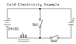
- L = 800 turns bifilar coil around a ferrite core, about 30 ohms
- C= 30μF, 4000VDC
In the above circuit, both the switches needs to be closed and opened briskly together.
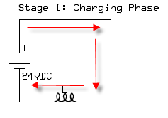
At the instant when the switches are closed, as per the standard rules the inductor would store the energy in the form of magnetic energy, this would result a high resistance across the battery, allowing no current to be consumed by the inductor.
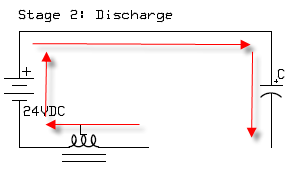
But as soon as the switches are opened, the capacitor could be seen getting charged up with a high voltage from the inductor.
Inductor Internal Energy Saturation
The question that arises is how the potential difference could reach across the capacitor with the switches being open and the circuit making no closed loop for the capacitor to charge up?
According to the author, in this example, the effect occurs due to the electrical energy which comes in contact with the resistance (open switch) wherein the current inside the inductance saturates the resistance.
Another source explains it in the following manner:
Creating Singularity Situation
With the switches closing and opening quickly, a singularity situation is created within the circuit due to the fact that the change in the current cannot be interrupted across the inductor.
Before the magnetic field across the inductor is able to die down, it experiences a voltage magnification across the coil.
This magnified voltage charges the capacitor without consuming any current from the battery.
The Ferroresonance Effect
This could be explained as the ferroresonance effect wherein as the core of the inductor is saturated, the potential moves in through an unconventional negative path, influencing the positive charge and prompting a negative entropic field to be induced inside the inductor which finally becomes responsible for charging up the capacitor.


Questions & Answers
I know this is very old now but i wanted to add that you can create cold electric effects without switches or “switching”.
The tesla hair pin and tesla coil can be imitated using nothing more than a rotated power line circuit.
I also find this circuit fascinating due to the fact it creates literal hot and cold nodes and its the cold nodes we tap to get “cold electric” effects.
Hello Swagatam,
My question is, why do we use a bifilar coil ? Can we also use a conventional inductor (with magnetic core) to get the same results ?
b- I checked these circuits, (especially RL) and I was not able to find where the free energy comes from. It is correct at t= 0, we have the applied potential across the inductor without any current flow, it seems that energy is not dissipated, but without current is it possible to build the magnetic field of the inductor, in other words to energize the coil? For infinitesimal time intervals, the used energy in the inductor is equal to the applied potential multiplied by time (Uxt).
Some free energy researchers claim to get more potential when they open the circuit, which is correct. But in such circuits the time constant is also changing, which is much less than the time constant of the switch-on circuit (for example circuits where a neon bulb is used).
Which again means that the integral of the inductor-potential over time – VL(t)dt is equal for the switch-on and switch-off times, which seems to be a conservative quantity as Vs = Weber = Tm².
So, if there is free energy in these back-emf circuits, where do these additional electrons come from and where can we see this in the equations?
On the other hand, ferroresonance may be a possibility to explain this phenomena, we can see a self sustaining circuit here:
https://www.youtube.com/watch?v=vgYLVyswgeQ&list=LL&index=39&ab_channel=AValon
Hello Birol,
Bifilar winding is not compulsory, it may be used only to enhance efficiency of the inductor. You can use any conventional coil with a magnetic core as long as the thickness of the wire is relatively thin, to minimize skin effect.
Honestly my knowledge of RL or LC circuits is very less, so i find it difficult to analyze these circuits, and therefore not in a position to discuss these concepts in depth.
Howdy ‘Swagatam’, I’m trying to replicate Don Smith’s Desktop power supply and Patrick Kelly’s
simpler version. My main question is the aircoils. Resonance attained by length of wire.
Would like to try having L1 and L2 both bifilar wound. Is it practical to do both, or does it work
better just 1 or the other? Also, all examples I’ve seen have the ‘jumper’ wire from end of 1st
wire to beginning of second wire ‘external’ to the coil. Any ill effects of running the jumper inside
the coil? That would allow the bifilar coil to be wound with 1 continuous wire with no joints.
Thus no diameter change to hinder the reflected wave. I’m 83, now, and took DeVry corresp.
back in ’61-’62. That led to large-scale computer programming for 32 yrs. Kinda rusty on current
‘school’. Would appreciate having someone to commune with. I survived all my old tecky friends.
Thanks much for any comments-help. (Kingman, Az is not a ‘tech. center’) ;).
Thanks Jeff, for your interesting question.
I have not yet investigated Don Smith’s circuit, still I will try to answer you with whatever little knowledge I have about inductors.
I don’t think there’s any problem having L1 and L2 both bifilar wound.
If in the original examples external jumpers are used in the coil then it should be just fine, however as you mentioned, a single continuous wire without joints looks a better and a more preferable option.
Wish you all the best, and keep up the good work!
Sir! Thanks much for the quick reply. Will try to improve my winding ability.
Sure, no problem Jeff!
But the “air” is not that thin. We have ZPE (zero point energy), aether, dark matter, liquid matter, endless magnetic waves, and energy brimming from every star. The transition or amplification of these energies hold the keys to this elusive power. It is there and can be harnessed. The entire universe and all that is in it vibrates, oscillates, and constantly moves. It does not violate any of the Laws. It is not energy from nothing, it is Something. Are you creating energy, probably not. But you can harness what is there and convert it to run our machines. It’s renewable, recyclable, and virtually endless. It may end one day, going over 13 billion years by our estimates to date. Is it “free”, no, but a lot cheaper than what we currently use.
Greetings to all
Just want to say about simple cold electricity circuit.
Does the energy between contacts get transferred magnetically.
Will ferromagnetic contacts work better.
Does positive back EMF side of coil make it stronger when it is at the north end of the coil.
I’m only asking about the circuit when it transferes energy.
Perhaps it is magnetic.
Greetings Drogonz, Sorry I have no idea about all these facts!
The way to create Cold Electricity is much simpler and effective that the circuit shown. When ever you pulse an inductor with a rapidly changing current an electro kinetic voltage is generated which opposes that change in current, as documented in Oleg D. Jefimenko’s book “Causality,Electromagnetic Induction and Gravitation”. This is popularly known as Lenz Law. But, Jefimenko shows in his book that that there is no causual connection between changing magnetic fields and changing electric fields. There only seems to be one because electric currents always have magnetic fields. This electro kinetic voltage is identically cold electricity.
By pulsing the gate of a MOSFET with a square wave of a signal generator, one can have a rapid switch. The faster the switching, the more effective. Only one is necessary, connect this MOSFET in series with a coil and a supply battery. On both ends of the coil place two fast recovery high voltage diodes so that the generated cold electricity can only flow in one direction. With fast switching, the electro kinetic voltage can rise to hundreds and even thousands of volts, depending on the frequency and Q of the coil. This even though one starts with a 12 volt battery! So, the MOSFET also has to be able to handle high voltage. The two high voltage diodes are than connected to a load, which often is a storage bank of batteries. The cold electricity can charge this bank of many batteries connected in series quite rapidly.
Rick Friedrich has demonstrated this phenomena many times and has powered an electric car and an electric boat with free electricity generated this way. He has also demonstrated that one can use resonate magnetic fields to multiply electrical energy as shown in this video:
youtube.com/watch?v=tpoOWs8SfVo&t=199s
Please provide more details. What kind of MOSFET? P or N Junction? Can you provide a circuit diagram to help clear things up? I looked at Rick’s videos but his videos are so long and on various topics that I can’t pinpoint where he specifically talks about the MOSFET and getting cold electricity. Please provide a circuit diagram.
What is missing in the above conversations is the source of the energy. Free energy by definition is energy which does not have to be paid for; eg electricity from the grid, expensive batteries, alternators driven by water, wind, or internal combustion engines.
As an example the atmosphere of the earth from ground zero up to the E layer has a voltage potential gradient. If this could be harvested, irrespective of the method it would surely represent free energy. The other problem I see is the comparison between magnetic force and energy, as derived from electricity- you can have one without the other.
Thanks for your feedback, appreciate it very much!
The ferroresonance theory makes sence, also consider these comments I saw on the EnergeticForum by th1138 and whatever you can find a no violation of conservation, modern relativistic quantum physics equivalent to level's and DavidE's posts mentioning Eric P. Dollard's "Dielectricity" or "Dielectric Power" as ideas to through out there..
http://www.energeticforum.com/renewable-energy/20265-what-cold-electricity.html
thanks!!
But why can't law of Conservation Of Energy explain to us WHY the Earth Is Hanging Up On NOTHING up till now while it keep moving Round the Sun 24/7?
Hmm, what sense does evolutionist who thougth no one created them have??
That you have not discover something does not mean the "something" do not exist. So it calls for humbleness before God the giver of life and creator of everything including Radio-active Materials.
But are this ordinary humans ready to submit to God so that He can make them discover more open but hidden things?
They said there god is gold, oil and diamond!!
How daft they are all including there so called scientists and professors alike!!!
everything has been proved beyond doubt by the great scientists so I think you need to investigate and research more regarding your questions, I am sure you'll be able to find all the answers with sufficient evidences.
the comforts of science and technology that you are enjoying today could become a reality and possible because of these great scientists…. so be courteous to them
I think the real juice in overunity motors lie in the homoplar motor concept. Bruce De Palma and Parahamsa Tiwari made such motors based on the dead short magnetized copper disc rotation concept that made few dc volts but at hundreds of amps.
thanks fidel,
presently I a studying the SEG made by mr. Tiwari, Ii looks interesting but I really fail to understand that if these are working why are these not getting quickly implemented for the needy ones…
its a very simple concept that faraday discovered over 200 years ago but many articles I read says such generators have virtually no back emf and doesn't slow down the drive motor when current is extracted from it unlike what the conventional generators do!! see Adam Trombly, Bruce De Palma sunburst machine, Parahamsa Tiwari (india)
that's interesting fidel, I'll do some research and try to find more regarding what the info
Hello Luis, please refer to the first diagram, it provides all the connection details of the proposed design
Hello sir:
Where is connected the other side of the bifilar bobine (L) ? My email is liahsuum@gmail.com.
Thank you!
I think the confusion here is between a force and energy, the parallel path is sharing the magnetizing force like the analogy with power disipated paralleled resitors. Using switchs in the resistor analogue ( could be a mostfets for example , reqires very little input current ( energy) to activate the switch gate to change the configuration of the resistors, but it causes what appears to be a non proportional increase in power dissipated between the series and parallel configuration (an apparent over unity increase in power dissipated) The power dissipated could be likenend to the non proportional increase in magnetic force because the force in one side is not the arithmetc sum of the forces in both sides even though it is assumed that it should be so intuitively or "by looking at it" . A force is not a source of energy so it has no value in perpetual motion or providing "free energy". Forces are often erroniously confused with energy because the are at the heart of most engines or electrical motors. Magnetic force is what causes the motor to turn – but Enerrgy by way of Voltage, Current and time applied to the motor which create the magnetic force that does the work of turning the rotor and applied load. Thermodynamics tells us that that energy has to be supplied somewhere for work to be done. Magnetism seems to confuse many people because, it appears to move heavy objects with little input energy, eg moving a strong magnet near to a heavier object will cause the heavy object to levitate a distance and stick to the magnet. However when all the forces and movements are properly vector added the net energy balances out ie the energy required to move the heavy object balances with ( always a slight loss according to Thermodynamics)the movement of the magnet and creation of the reaction force inholding the magnet from moving toward the heavy object. This must be the case otherwise we would have had "free energy " for 150 years or more since the nature of energy was formally understood. I will remain a sceptic untill someone produces a motor using the principles demonstrated with the "parallel magnetic circuit phenomena" that actually produces more energy than it consumes. I think anyone would struggle to even produce a motor that had unity energy consumption using this principle , let alone over unity which I believe in every case is impossible. I am however sure that the principle may have applications in making different and smaller motor geometries as you said to deliver more power from an energy source.There have been some quite astounding attempts or fundamental misunderstandings using magnetic force to hoodwink investors into "free Energy" concepts. Like you though, I think also that science teaches us that it would be wrong to rule out the possiblity of other sources of energy available in the universe for us to exploit – perhaps by tapping into the so called "dark energy" that is causing space/time to rip itself apart possibly —– but that may also be to do with the final depletion of the source of all energy in the universe, and is therefor only a very small, low quality energy source, that is only available on useful amounts , over the vast distances of space time and hence only of little practical use. I think you can still be rest assured that even the laws of Thermodynamics will still apply to such an energy source !!!
Thanks Johanus,
I'll take that! Actually I have no answer to your following statement:
"I will remain a sceptic untill someone produces a motor using the principles demonstrated with the "parallel magnetic circuit phenomena" that actually produces more energy than it consumes. I think anyone would struggle to even produce a motor that had unity energy consumption using this principle…."
Although I have tested the basic model of the parallel path device and could successfully mobilize the magnetic force, however I was not completely satified as the ends could pull a ferromagnetic substance only when it was brought too close to the ends, which made me lose interest in the experiment.
You've explained it wonderfully, I am sure this would make many enthusiasts sad, but truth is what all must face and agree to:)
Hmmm – Yes I have looked briefly at the parallel magnetism path on your site. Interesting at first glance, however two point come to mind, 1) A magnetic Force is not a source of energy, it is simply a force the two concepts are quite different and are often confused. 2) the switching of the force with apparent magnification I am pretty sure can be explained by fundamental electromagnetic theory.
What we see is an apparent "over Unity" creation of a force – not energy which would be something to get excited about. I think the 4 X increase in force can be excplained by an analogy to power in an electrical circuit with a constant voltage applied ( equivalent to the magnetising force) to a series / parallel connected resistive load whereby the power dissipated appears to increase dispropotionately depending on whether the load resistors are connected in series or parallel. EG An applied circuit voltage of 1 volt with 2 resistors of 1 ohm in series dissipates a power of 1 / 1=1 = 0.5 watt whereas the disipation with the same resistors in parallel produce 1 / 0.5 = 2 watts.More power magically from the same voltage???? !! – but we all know the current has increased, the power source is working 4 times harder so no net gain of energy from nowhere. could it be explained by something along those lines? – The laws of magnetics are different in terms of the force increase ( equivalent to the power increase above) – but principly follow a similar behaviour
…just to add, your voltage/resistor theory does not explain the over 100% efficiency, so I am afraid the example can not be compared with the parallel path theory.
Thanks Johanus, yes you are right it may not be the kind if free energy that we normally talk about, but nevertheless the concept looks extremely useful due to a couple of reasons:
first it promises to produce over 100% efficiency that's as good as acquiring free energy,
second, the electrical pulses just needs to be in fractions, and not in a sustained manner in order to make the magnetic power hold on at the relevant ends,
meaning if the magnetic force is supposed to stay for say 1 second on each side, could be implemented by supplying electrical pulses at the rate of may be 1/10th of the duration, that is just for 0.1 seconds, that looks interesting.
Yes a good idea too Swagatam,, it is interesting how many circuits like this appear on the internet claiming to tap into free "Zero point "energy. Some of the worst claims come in the form of electrolysis where the publishers seriously claim they can "produce" free energy from Hydrogen/ oxygen using pulsed current. There was even a serious investment made here in the UK into a device that claimed to produce heat from current passed through water – it claimed that by using a pulsed waveform more heat energy was liberated from the water than was supplied by the electrical power source!!. Much of the confusion in this type of device is caused by using simple average reading ammeters to measure pulsed or not sinusoidual current waveforms, causing the actual current measured on the instrument to be much lower than the true RMS value.
However,It is quite staggering how many who are supposed to be degree level qualified in electrical engineering can not see this simple error!!
Anyway – Like you I think is it is always interesting and amusing to look at these"wonder" circuits that claim to have magical free energy properties!!. I agree with you , there is sometimes much to be learned by discussion , by way of analysing them from fundamental principles.
There is only one acid test that they must all pass to qualify as a Free Energy device – and that is the Laws of Thermodynamics – Everyone that has been published that I have encountered has failed miserably!!!
.
You have a good, thought provoking website – even though as you clearly state ,some of your circuits need a little work to produce a practicle design – they all based on a good starting point from what I see
Thank you Johanus, since ages we all have loved and wanted to see things which could be perpetual by nature and produce sustaining outputs without a sustained input, this craze inspired and led to the development of various such concepts, many enthusiasts tried to do them seriously while some just to fool the common folks and make some easy money.
Although I still believe that someday somebody would be able to find an out of the way concept which would be in line with the laws of thermodynamics yet give the required perpetual kind of results, until now this is only in our dreams.
The best one created so far is the parallel path magnetic concept which was very cleverly done by Mr. Joe Flynn and can be considered the most promising and legit overunity technology to date. I have myself tested the basic prototype and it really worked, as explained here:
https://www.homemade-circuits.com/2014/02/can-parallel-path-magnetic-technology.html
As long as skeptics like us exist new claims and concepts will be tested to their limits which is good for all of us and science…I appreciate your inputs!
Trust me there is nothing mystical or magic about the ahis circuit configuration. Its operation can be explained by established rules of physics. The Ideal that a coil can be charged with energy without taking any from the sourcrce ( battery in thiscase) issimply wrong.In the instant that the switches are closed, the current in the battery / coil circuit will grow exponentially from zero – so as long as the switch is closed for any period, som energy will be held in the magnetic field surrounding the coil.If the coil has a core made of a magnetic material this will change the period of time and the amount of energy held in the field. when the switch is opened the field will collapse causing a voltage of reversed polarity to appear across the ends of the coil. I believe the switching show is wrong for the claimed phenomena to arrise – probably through some misunderstanding of the switch connection. If the spDT switch was wired such that when the coil switch is closed, the capacitor switch is open and vice versa, then on opening the coil switch, the capacitor switch closes, allowing the high voltage produced by the collapsing field to be transfered in proportion to kirchoff's laws onto the capacitor, however the switch must be switch back again immediately for this voltage to be maintained ( measutred only by a high impedance voltmeter to assure the experimenter it is present). If am awrong and the spdt switches are wired as described, the reason for the presence of high voltage is purely down to the mechanical rrangement in the spdt switch allowing the capacitor switch to open slightly after the coil switch. If this is the case – then the circuit can not always be relied upon to work as it depends purely on the switches mechanical properties. I will finally re assert that the statement in the article above :- "the inductor would store the energy in the form of magnetic energy, this would result a high resistance across the battery, allowing no current to be consumed by the inductor." is simply wrong – if magnetic energy is formed in the coil , it can only come from the battery in the form of voltage and current over a time period ( E = V x I x t).
Sir, there's indeed how to create energy from thin air. And it's very simple, you can do it with supplies available anywhere. The only problem: the output voltage is only 1,5 v, maybe less.
That's a valid explanation, I too believe in the fact that energy cannot be created from thin air, it has to have a source….in this case the battery is the source so nothing's intriguing or mystical about the phenomenon.
Actually I picked it from an online source and presented it here for further assessment and to get individual reactions from the readers.
Good day Vijilan,
I have explained the circuit comprehensively, so please troubleshoot by referring to it point by point. It will be difficult for me to suggest without practically checking it.