Mini black and white cameras are now available at a low cost. The proposed experimental setup allows wireless transmission of images from a CCD camera module. The entire system is completely autonomous, and numerous applications can be considered: video doorbell, monitoring of a child's room, onboard video system, aerial photography (modeling), etc. The transmission is done in the UHF band; a simple television with an antenna will be necessary for receiving the images.
The CCD camera module delivers a normalized video signal of TV, created at a frequency of 75 Ω. This is a composite video signal, meaning it is composed of the signal corresponding to the captured images (useful part) and signals like visualization (sync line and frame sync, suppressions).
The signal complies with the "name" CCIR (Consultative Committee of International Radiocommunication: an organization that provides recommendations on television systems to facilitate exchanges between different countries).
This signal cannot propagate directly through the airwaves. Only a high-frequency signal can carry the information through the air.
The setup, therefore, involves transmitting an HF signal (called the carrier) modulated by the video signal.
Its radio-electric characteristics will be low power and have a limited range (a few tens of meters approximately).
Frequency Ranges
Choice of the frequency range of transmission and the type of modulation [Table 1]: The selection of the signal range and modulation type [Table 1] is performed using the UHF (Ultra High Frequency) tuner of the television.
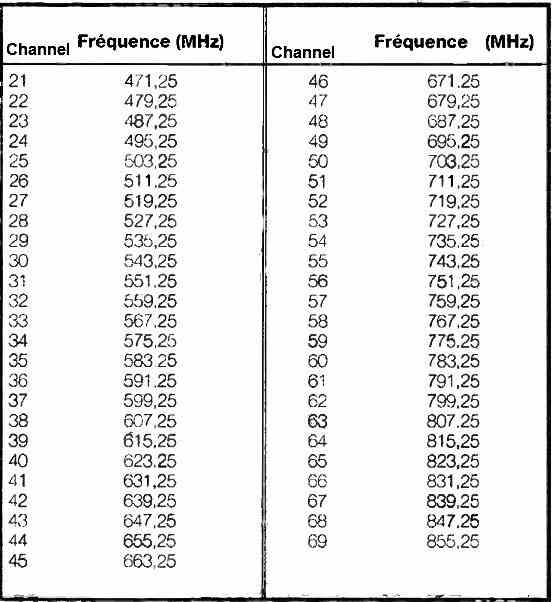
The available frequencies for television broadcasting have been planned in different bands (VHF I-III and UHF IV-V), consisting of 8 MHz wide channels. Table 1 provides the correspondence between the channel and the image frequency for the UHF band used in the setup.
Circuit Diagram
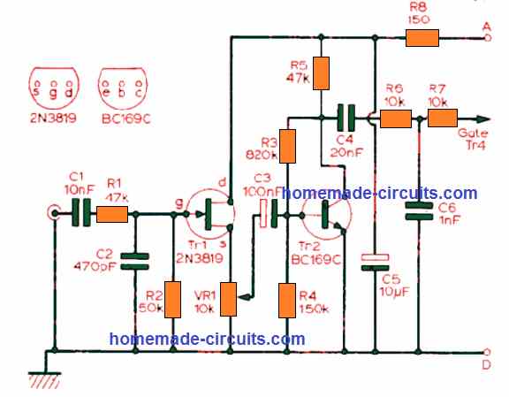
The circuit diagram shown in the figure below has been chosen for its simplicity (3 transistors) and low cost for an experimental setup.
The local oscillator is based on an L, C oscillator circuit of the Colpitts type, complete with a frequency doubler. A resonant L, C circuit (tuning circuit) is used as the load for the common-emitter transistor T1. The capacitor C3 provides feedback to sustain the oscillations. The carrier frequency is determined by the formula:
fo = 1 / 2π√LC
Where L is equal to L1, and C is a function of C2, C3, and C4.
The variable capacitor C allows for adjusting the carrier frequency, which is the emission frequency. The BFR91 transistors used are well-suited for this type of high-frequency application.
The video signal modulates the UHF carrier in the final amplifier stage based on transistor T3, whose output power is intentionally limited.
This signal is first filtered by the R10/C10 network (a low-pass filter with a cutoff frequency of 3.4 MHz).
The camera module is powered by 12V, and the Ra1/DZ1 combination stabilizes the power supply voltage of the transmitter module.
Construction
The circuit layout and its implementation are shown in the following figures. It is a single-sided circuit with dimensions identical to those of the camera module.
Therefore, it is possible to connect them using two spacers to achieve a very compact assembly.
Due to the small size of the circuit, careful and precise soldering of components is required. It is recommended to use a fine-tip soldering iron and thin-diameter solder (0.7 mm).
However, solder bridges may form between a component pad and the ground plane. In such cases, the bridge should be removed using a desoldering pump or braid, followed by re-soldering.
As usual, the components should be soldered in ascending order of height (resistors, diode, transistors, inductors, capacitors, power wires, and antenna wires).
Transistors T1 and T2 are correctly placed when their markings are visible. Creating the three inductors L1, L2, and L3 is straightforward by winding three turns (two turns for L3) of enameled wire with a diameter of 0.7 mm around a cylinder with a diameter of 3 mm (e.g., miniature potentiometer shaft or drill).
Then, the turns are separated to adjust the length to 3 mm (2 mm for L3). To establish good contact during placement on the circuit board, remember to scrape off the varnish to expose the copper.
The antenna will consist of a single wire of about thirty centimeters in length.
Fine-tuning/usage
After visual and electrical verification, position the capacitor C2 and the resistor R9 at the midpoint. Then, power the setup with 12V. The power consumption of the camera/transmitter assembly is approximately 200mA. An 8-cell battery pack (1.5V each), a small 12V battery, or a mains adapter (for a fixed application) can be used. Pay close attention to the polarity of the power supply for the assembly to avoid damaging the camera module.
Once the camera/transmitter assembly is powered, two possibilities arise for adjusting the television.
Procedure #1: Manually select an unused channel (between 21 and 69) not used by regional transmitters. Then, adjust the capacitor C2 until the images appear on the screen.
Procedure #2: Use the automatic channel search until the images appear on the screen. In this case, multiple attempts may be necessary as the setup should not interfere with TV channels.
Finally, refine the image quality by adjusting the resistor R2. The tests have shown satisfactory image transmission quality over a distance of about twenty meters.
The environment (buildings, walls, etc.) significantly affects the range, making it difficult to provide an exact transmission distance.
Increasing the range can be achieved by modifying the characteristics of the output amplifier (changing the value of R7).
However, it should be noted that radio signal transmission is subject to administrative regulations (Postal and Telecommunications Code).


Questions & Answers
How to receive the output ? like after making this what do i need to see the output?
You can receive the output on any standard TV with antenna….please read the Fine-tuning/usage section….
i want to make it as my college project but i don’t have any tv so is there any alternate option?
The video transmitter is supposed to be tested on a TV, without a TV you cannot verify the results…
Just found this site. Thank you a million, a lot of work has been done on all these pages!
Thank you so much, Glad you found the site helpful…
Hello, i’m trying to build a wireless video transmitter and receiver module. Your help would be appreciated in this matter.
Hi, I really wish I could help you with your project, however I do not have sufficient expertise in the field of video transmission, so it might be difficult for me to provide a comprehensive guidance in this field.