The post comprehensively discusses a basic Arduino code implementation guide for blinking its on-board LED. The data was built, tested, and written by Jack Franko.
CODE: for simply inbuilt LED on pin 13 of ARDUINO BOARD by default it is programed to blink frequently at 50 Mili Seconds as it in description it will be stated asms (milliseconds).
/* first Simple
Program on Arudino BY JACKFRANKO */
int l = 13;

//where l is pin 13void setup(){  pinMode

(l,OUTPUT); }void loop() {  digitalWrite

(l,HIGH);  delay(50);  digitalWrite

(l,LOW);  delay(50);}
Note :As we are studying an Arduino UNO R3 Board Programing if you are not a programmer or a designer or a hobbyist, as a student you must start from the basics.
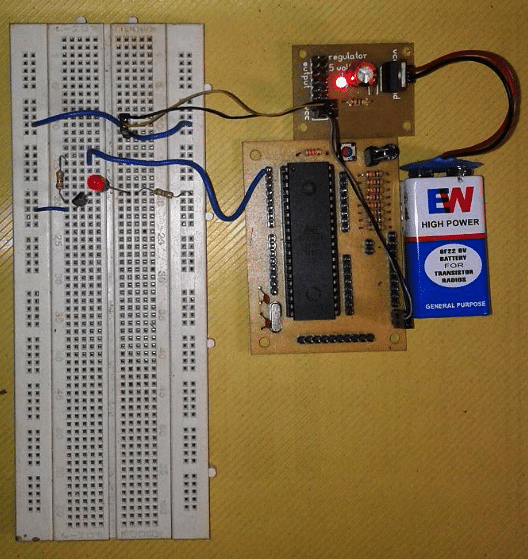
The first thing is to understand the Arduino Uno R3 by getting a kit which is available on online shops.
Description :
as by tradition it is to get our name before the program starts is an good IDEA , here is my first basic program which is stated above has started with this sign /* and the text of name and all stuff you want to type between it */ is which does not affect the program and it is not a part of program because the Arduino program Compiler knows that the stuff between “/*,*/ “ mark must skip, it’s just the title for program.
/* first Simple
Program on Arudino BY JACKFRANKO */Next Line int l = 13;
//where l is pin 13
It is a Declaration part of the program where we are going to declare the integer with command “int “ followed by small alphabet L which is equal to 13 and ended with semicolon then after double slash “//” and some text.
Here we had given command “int” which we usually say integer and small L equal to 13 and we ended with semicolon here we said to compiler that the value “l ” is equal to 13 which is located at pin no. thirteen on the arduino board , here “l ” is just a value which is designated to pin no 13 , that “l ” is not any function or script for compiler, it is for us to make code little bit friendly that “l ” in this project is a short for LED.
I want to make code little smaller and save some space. At this point if you don’t want to keep it as “l ” then say that you want to keep it for i.e “me” then in the whole code where ever there is “l ” you have to change it “ me ” otherwise the compiler will not work and it will give you error.
This statement consist of second part which is followed by “// “and some text here we need to understand that whatever statements are followed by “//” at opening and didn't have any closing, the compiler will not read that statement. It can be in multiple lines without closing. This is for us to give some reference and notes in code for understanding.
Before understanding the rest part of the code we must understand the basic functions of code and that are “void setup “ and “void loop” here these two functions are very important because we are going to declare our INPUT, OUTPUT and what type of work done by in it . so let’s start with void setup , this is a part of code where we are going to state our INPUTS & OUTPUTS which must run once for our project. Here we are going to talk about only one output as per our code.
The Other function void loop is the second part of the code which is going to run in the form of loop . here these both functions consist curve bracket open and closed and then after curly bracket open holding some code and curly bracket close. I will give information about these bracket in next program . here we have to focus on curly brackets where we have some code enclosed between these brackets.
void setup(){  pinMode

(l,OUTPUT); }
Here we have stated the function which must run once for our project and that as our output. if You have noticed that we have written our code in curly brackets where we have declared pinMode l is output in curve brackets and ended with semicolon,
here pinMode is function designated to integer l as OUTPUT.
Hence l is designated to pin no 13 on arduino compiler will understand that pin no 13 is called l and l is pin no 13 if we put 13 at the place of l after PinMode function
as output it will consider both 13 as well as l.
if we delete int l = 13 it will not consider alphabet l and it will give you an error. Here we had set pin
no 13 which is alphabet l as output, it's always written in uppercase letter as OUTPUT and function pinmode is written in pinMode starting with small letter without space, other word Mode starting with uppercase letter which is understood by the compiler which is case sensitive.
Next we come to loop mode of our program here we state all that function which must run in loop
for a unlimited long time.
void loop() {  digitalWrite

(l,HIGH);  delay(50);  digitalWrite

(l,LOW);  delay(50);}
Here we had declared integer l to HIGH with the function digitalWrite. This statement digitalWrite will make integer l HIGH means when ON it will turn ON pin no13 on Arduino board as we had stated pin no 13 is l which is separated by comma in the curve brackets.
Here after we said that delay (50); this statement will count time in ms (millisecond) where 1000ms is equal to 1 second. In this program I want my led to flash 20 time in one second mathematical calculation
gave me a value 50 which is enclosed in brackets.
This means under the loop section first line will turn on my LED located at pin no 13 and wait for 5ms. If we didn't give further function to loop to turn OFF the LED it will remain ON.
Though we had said that delay for 50ms. So we have given a command to turn OFF the LED
in digitalWrite (l,LOW) , after stating this statement LED will not turn OFF because the loop is incomplete without delay (50); first we turn on the LED then we wait for 50ms then we turn OFF led and then we wait for 50ms to complete the one loop which is going to play for a infintely as long as the Arduino is powered. It will turn ON & OFF your led at pin no
13 for 20 times per seconds.


Comments
dear sir
i want to make 12vdc 1 led circuit led on time 10 microseconds or off time 1 seconds Please sir help me send circuit Diagram
Dear Deepak, you can try any IC 555 astable circuit and adjust its ON time/OFF time accordingly….you can take the help of any "online 555 calculator software" for selecting the components.