This simple automotive electrical fault finder probe circuit will enable you to solve most electrical troubleshooting in your cars, tempos, motorcycles etc with a lot of ease and in a hassle free manner.
The idea is very simple. The circuit exploits the high impedance gate value of the MOSFET which makes the circuit extremely sensitive to voltage levels, so that it is able to detect even the slightest bit of continuity.
The probe point is used for locating the faulty line running anywhere in the electrical system. The probe point can be touched where a continuity is to be detected.
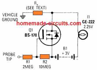
Our hand holding the probe body connects our body with the junction of the MOSFET drain and the lamp. Our other hand is supposed to be touched to one of the known earth point of the car chassis. With this arrangement, the troubleshooting process can be commenced, and if the probe locates even the slightest of continuity, it will cause the lamp to light up.
In the circuit for the automotive fault finder probe, the resistor Rx indicates the resistance of our body. This depicts, one hand holding or touching the drain side of the MOSFET while the other hand resting on the chassis of the car, or the car body.
Construction
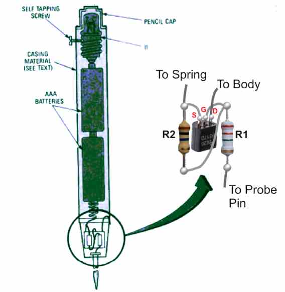
The construction of the car electrical fault finder probe can be see in the above picture.
The body of the unit is actually made up of a metallic substance, such as steel or copper or aluminum. The MOSFET and the resistor assembly is housed inside a plastic cap and fitted at the lower end of the metal body. A tinned copper wire is used as the probe point fitted on the other end of the plastic cap.
A sel-tapping screw is used for connecting the metal body with the drain connection of the MOSFeT and the lamp.
How the Circuit Works
Suppose the user wants to locate the continuity of an earth wire across the electrical wiring, which might have lost its contact to a specific electrical gadget.
The user holds the probe with his one hand, so that the body comes in contact with the MOSFET drain and the 3V from the lamp.
Next, he holds the car body, so that the 3V battery positive from his body enters the car body. After this the probe point is touched to the different wires for tracing the continuity.
As long as a continuity is present, the probe's +3V from the user's body passing through the car body reaches the probe point, and the MOSFET gets the required gate voltage, which keeps the lamp illuminated.
However, once the probe reaches a point where the probe lamp stops illuminating will indicate towards the broken continuity point., and the user can quickly troubleshoot the area by correcting the cable joint appropriately.
Car Electrical Fault Finder using IC 741
This handy car electrical fault finder probe was created as a part of an inexpensive test equipment to keep in car tool box for an on-the-spot electrical system debugging. It may be created in a variety of styles to meet the needs of the particular consumer. The probe's primary section is made up of of two LEDs that display the health of any wiring in the car.
When the probe is unconnected, two LEDs illuminate, representing a voltage level that is neither positive nor negative. When the probe is attached to a contact that has a certain voltage state, the relevant LED will illuminate and the other one will turn off.
Voltage detection
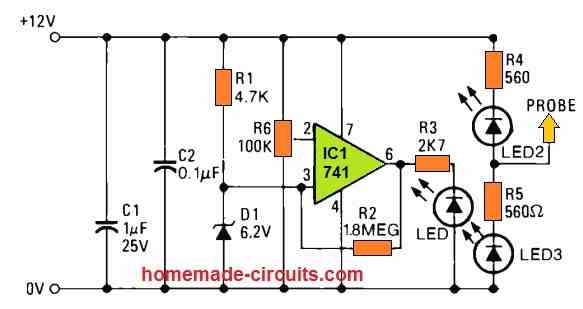
The probe's second stage is a voltage detecting circuit that employs a 741 operational amplifier to monitor when the voltage across the automobile battery exceeds 12.5 volts. This gives a quick method to see if the battery is charging.
It is clear how LEDs 2 and 3 sense voltage levels. Both are wired in series with the current-limiting resistors R4 and R5.
As soon as the probe is linked to a positive or negative voltage, one of the LEDs is virtually shorted out, keeping only the other LED switched on.
Circuit of a Comparator
A 741 op amp IC is implemented as a comparator in the second stage of the circuit. As soon as the voltage on one input increases above the voltage on the other, the output state toggles.
The input on pin 3 detects a reference voltage over Zener diode D1, and pot R6 is utilized to establish the necessary voltage on pin 2. Once the battery voltage decreases, the voltage on pin 2 falls below the potential on pin 3, prompting the output to go high and illuminating LED 1, which is designated as CHARGING.
Testing the Probe
After completing the circuit, it must be tested by first placing R6 to the center of its range and coupling a variable-voltage supply and a voltmeter across C2.
Now, with the car tester circuit switched on, if you adjust a voltage between 6 and 12 volts, LED1 illuminates (or turns off). The preset is at this moment is set such that the LED only illuminates when the supply voltage reaches 12.5 volts.
Ignition Timing
Put the testing probe in the glove compartment or trunk of your car. In the event of a power outage, you'll always have it quickly accessible. It may also be utilized to detect the exact moment the CDI contacts open, allowing for precise static ignition timing.


Comments
I think the leds are drawn the wrong way around. The + and – 12 volts, is it powered from a separate battery or car battery?
You are right, the LED polarity for the 741 IC circuit must be turned upside down. The 12V supply is taken from the car battery
dear sir,
Nice project for my son since he ‘s a car mechanic. i’m interested in making one but i need to know is there
any other equivalent mosfet bs170 can i use.
TQVM
Thank you Dear Omar, you can search on Google regarding “Small Signal MOSFET Datasheet”, you will be able to find a few equivalents which you can use for this project