With temperature, if there is one characteristic physical quantity of the past or future weather, it is certainly atmospheric pressure. The variations of this quantity are particularly interesting for weather forecasting: a decrease in pressure invariably heralds the arrival of rain, while a significant increase is a certain sign of improvement or persistent good weather.
The exact value of atmospheric pressure is not sought here; rather, we will focus more on visualizing the evolution of this quantity, comparing it to a moving index, much like the reference needle found on a mechanical barometer in a living room.
Atmospheric Pressure
The concept of atmospheric pressure is essential in weather forecasting. Although not easily tangible, this physical quantity is simple to demonstrate.
At sea level, atmospheric pressure is strong enough to lift a column of water to a height of about 10 meters, or a column of mercury, which is significantly heavier, to only 76 centimeters for a surface area of 1 square centimeter.
Therefore, a mercury barometer is nothing more than a bent glass tube, open on one end and filled with mercury.
It is calibrated in millimeters, which represent the weight (i.e., the pressure) more or less exerted on the Earth's surface.
This device still bears the name of its inventor, Torricelli (1608-1647), a disciple of the famous Galileo.
Air pressure can increase or decrease. It's worth noting that the value of atmospheric pressure also provides a good indication of altitude.
In essence, an altimeter is a type of barometer calibrated in kilometers.
It is unfortunate that temperature also affects this measurement because colder air, being heavier, tends to descend, while warm air expands and rises, being lighter.
One can expect a decrease of approximately 1 millibar for every 8-meter increase in altitude.
In the International System of Units (SI), the unit of pressure is the pascal (Pa), which represents a force of 1 newton per square meter (approximately 102 grams).
However, this value is not commonly used and is often replaced by the bar, which is equal to 100,000 pascals.
The standard atmospheric pressure is an average value, approximately 1.013 bars or 1,013 millibars.
This unit is often displayed on household barometers, along with the value 76, representing the height in centimeters of the mercury column at sea level.
But that's not all! The millibar has been replaced by the hectopascal (hPa), perhaps in honor of the memory of the great physicist Blaise Pascal.
In the market, one can find metallic barometers or aneroid barometers, which operate based on the elasticity of metals.
A metal chamber, devoid of air, is subjected to the atmospheric pressure to be measured. Using a lever, it moves a small needle across a calibrated dial.
A movable cursor allows one to "store" a given pressure and later check whether it is decreasing or increasing. Based on these observations, we propose constructing our barometric indicator.
The Electronic Atmospheric Pressure Sensor
Nowadays, to measure atmospheric pressure in a fully electronic manner, it is sufficient to "weigh" the weight of the air column exerting pressure on the sensitive surface of a sensor, exploiting the piezoresistive properties of a tiny silicon wafer.
It is similar to a miniature strain gauge capable of detecting minute variations in mass on its active surface.
Motorola has been offering a highly interesting component to the general public for several years now, which is temperature compensated and precisely calibrated at the factory using a laser beam.
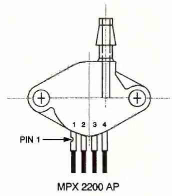
This component is the absolute pressure sensor with the reference MPX 2200AP.
A special model with two inputs measures differential pressure to, for example, estimate the water level in a tank. The typical sensitivity of the sensor is 0.2 mV per kilopascal of pressure.
Thus, at the exact pressure of 1 bar = 1000 hPa, the output voltage of the component measures precisely 100 x 0.2 mV = 20 mV.
How the Circuit Works
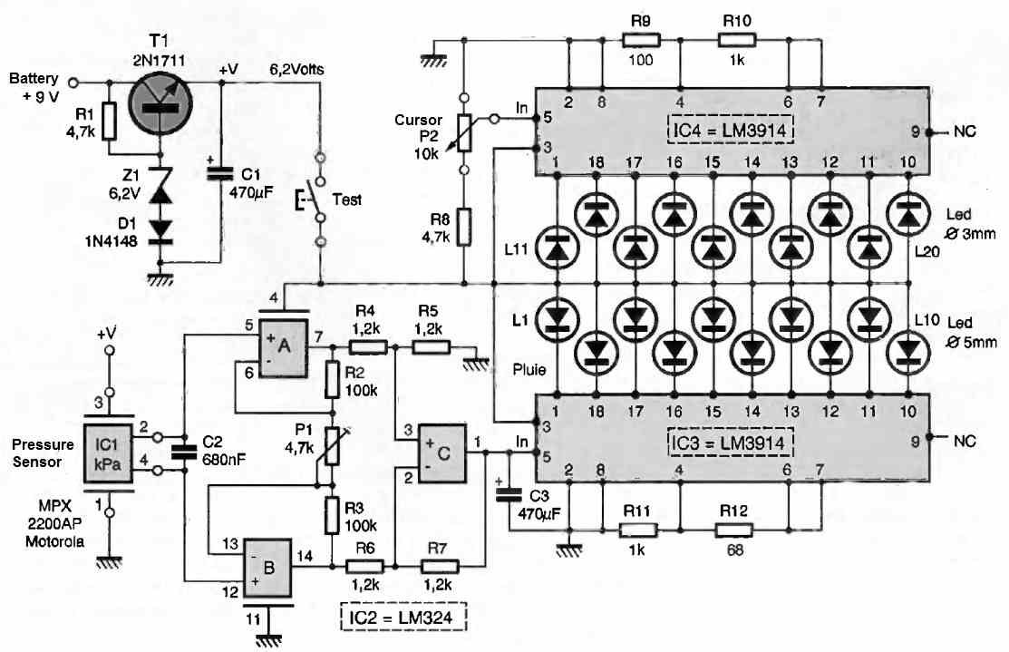
The atmospheric pressure indicator circuit is presented in its entirety in the following figure and consists of three distinct sections: the regulated power supply, the measurement and amplification section, and finally the display device and memory cursor.
The intermittent power supply of this device allows the use of a 9V rectangular battery.
To eliminate any voltage variations due to battery wear, we have a voltage regulation device consisting of the ballast transistor T1 and the zener diode Z1 with a nominal value of 6.2V. The switching diode D1, connected in series, precisely compensates for the voltage drop across the PN junction of the transistor.
The large-value electrolytic capacitor C1 also stabilizes this continuous voltage at 6.2V.
The positive terminal of this power source passes through the TEST button, which only powers the display device upon request, contributing to a significant extension of the battery life.
The pressure sensor IC1 has 4 aligned pins: pins 1 and 3 directly receive the sensor's power supply voltage, while pins 2 and 4 deliver the useful signal, which will be transmitted to a simplified differential amplifier with a gain of 50.
Since we do not need to precisely measure this voltage, there is no provision for a digital display of this value.
However, on pin 1 of the operational amplifier (ACP) C, the exact value of the atmospheric pressure can be determined using a digital multimeter when the amplification stage gain has been precisely set to 50 by adjusting the P1 element.
The output stage is dual: it utilizes two well-known circuits, LM3914, each consisting of 10 linearly varying comparator stages.
This very practical component directly controls 10 light-emitting diodes (LEDs) as the voltage on the circuit's input 5 changes.
By not connecting pin 9, it allows for a dot-by-dot display, meaning one LED at a time. On the IC4 circuit, the operation of the external potentiometer P2 varies the input voltage and allows for manual activation of one of the 10 LEDs (L11 to L20).
This part of the schematic obviously corresponds to the movable cursor of the mechanical barometer.
The IC3 circuit, naturally, receives the DC voltage from the pressure sensor and amplifies it approximately 50 times. It is responsible for indicating the approximate value of atmospheric pressure by lighting up one of the LEDs (L1 to L10).
How to Build
The layout of the copper traces at a 1:1 scale is provided in the following figures for perfect reproduction using the photographic method.
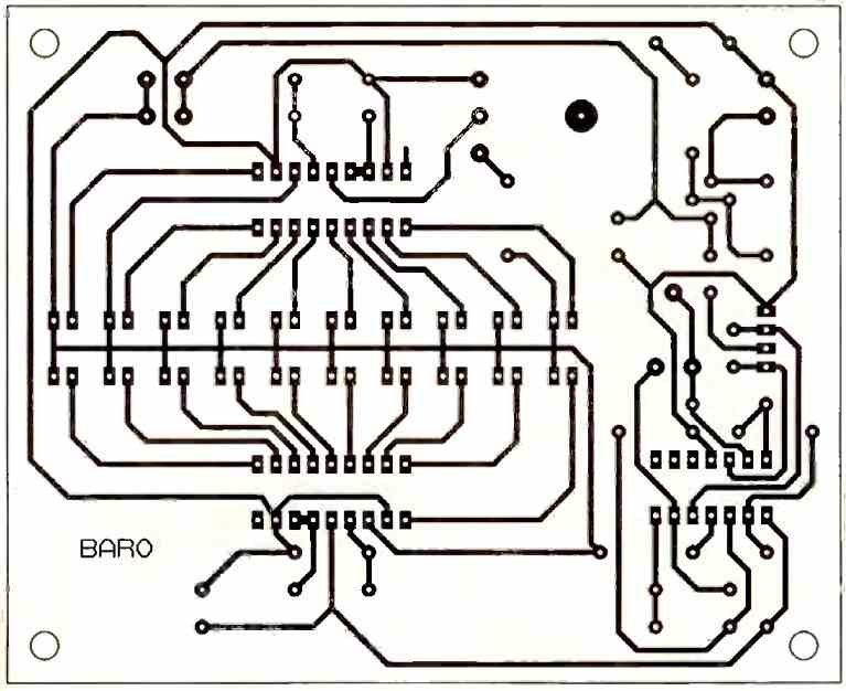
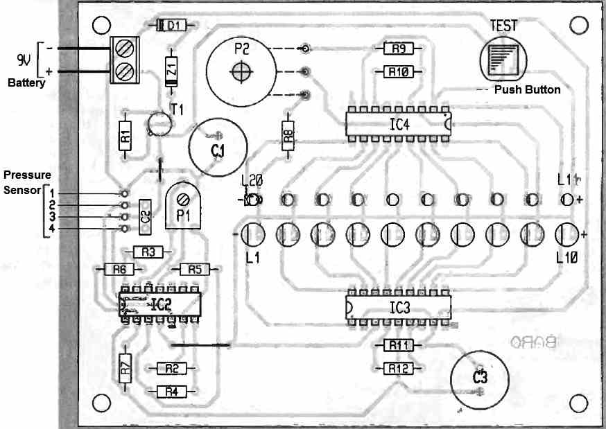
This board accommodates all the components from the schematic.
The pressure sensor is simply inserted vertically into a 4-pin tulip socket; care should be taken to align the notch of the sensor with pin 1.
The control button is also located on the board but can be mounted on the front panel of a potential enclosure, along with the adjustable potentiometer P2 equipped with a control knob.
It is important for diodes L1 to L20 to be arranged in two parallel rows to allow for easy reading of both the atmospheric pressure (P.A.) and its memorization through the movable cursor.
How to Adjust
The adjustment of this LED barometer atmospheric pressure indicator circuit involves obtaining sufficient gain on the amplifier through the adjustable P1.
If you place a voltmeter between pins 2 and 4 of the sensor, you can observe the approximate gain and the value of the barometric pressure at the output across capacitor C4.
Remember that it is the variation of this physical quantity that allows for some predictions, rather than the precision of the adjustment.
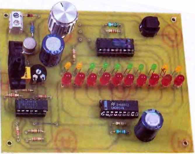
Tested Prototype
The completed and tested prototype of the above explained atmospheric pressure indicator circuit can be seen in the following image.

Need Help? Please Leave a Comment! We value your input—Kindly keep it relevant to the above topic!