In this post I have explained a simple deep under soil metal detector circuit for evaluating hidden metals such as gold, iron, tin, brass etc by detecting change in the resistance of the relevant soil layers.
Bigger physical objects which might be buried within the topsoil could be unveiled through a modification in the electrical resistance of the soil layer at various depths. The design is about a device which may be for implementing relative enhancements on the resistance of the soil. This particular application can be particularly handy in archaeological excavations.
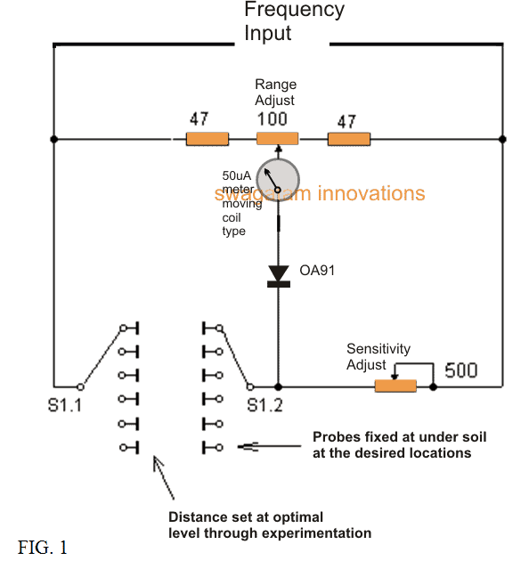
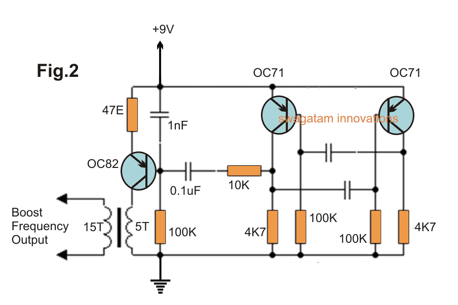
The proposed deep soil metal detector instrument includes the measuring bridge (figure 1), the alternating voltage generator (fig 2) and the a couple of probes, sunken inside the soil.
The resistances across the soil layers, between the electrodes of probes are coupled to the input of the bridge arms, for measuring the parameters.
Prior to measurement through 100 ohm resistor may be adjusted for bridging the balance so that the dial instrument readings are initially at the minimal.
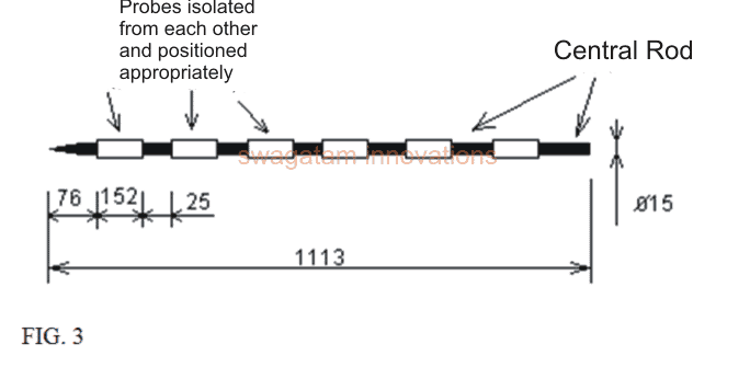
The design of the probe represented in FIG.3 may e understood as follows:
Each of the probes signifies the insulated rods having a diameter of around 1.5 mm. on the surface area of the bar along its axle, these are fixed electrodes in the form of six thin-walled tube, separated from each other.
Each electrode probe with the aid of six cable connection is attached to the switch S1 measuring bridge, that in turn hooks up with one of the six pairs of electrodes together with the bridge.In this instance, each pair of electrodes at each of the positions of the switch S1 corresponds to the precise depth of the soil layer.
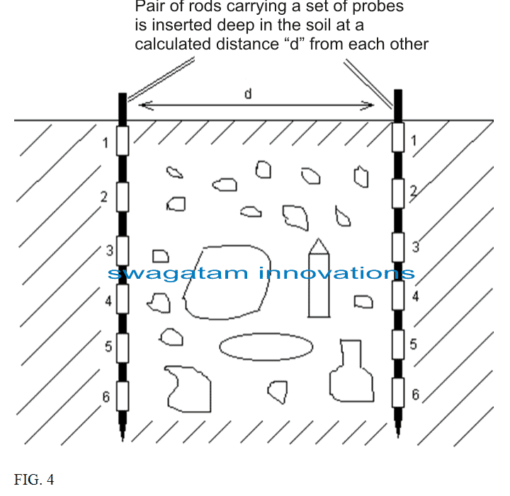
Soon after placing the probe on earth, in accordance with FIG. 4, the electrical resistance of the subsequent layers of soil located different depth is detected.
Evaluating the values acquired from the resistance, you are able to draw a conclusion at what depth (which soil layer) are objects that might be changing the resistance of the soil.
The space between the probes are pretty much decided on in each specific scenario. Occasionally, great outcomes could be obtained with distance that me approximately close to 2.4 m.
The variable resistor of the bridge is 500 ohms as shown in the deep soil metal detector circuit diagram, is for controlling the sensitivity of the bridge depending on soil type being investigated.
Courtesy: The Radio-Constructor, 1966, 8


Questions & Answers
Kindly elaborate on the probe rods
The details are provided in the article, please specify what you are not able to understand…?
how is the insulation on the rod works ?
hi , i’m from Algeria , self made in electronics , my interest for metal detector is big and i wanna know few things
1/ when we design any pulse induction or vlf or I.B metal detector i would know especially for P.I , what are the criteria when we put for exemple 100mH or 200mH or any Henry value or à given coil ? for exemple , i make a P.I with NE 555 IRF 9640 and 40 cm round coil , on the web i found ” common P.I search coil table ” and for a 40 cm coil , they give : 40mm – round – 17 turns – wire size: 0,50 mm/0,20 mm2 – 396 µHenrys – 1,8 ohms , on what do they base themselves to fix these values? because I want to build my own coils, what is the theorem to make my own coils
thank you
Hi, unfortunately I myself do not have any expertise in the field of metal detectors, so it can be difficult for me to solve your query. I hope someone else on this platform will be able to understand and provide an appropriate solution to your query.
dera sir what type transformer have to be use thank you ,,,,,,,,,,,,,,
It can be a ferrite torroid ring with the winding numbers as indicated in the diagram.
Good afternoon Mr Swagatam and I thank you Isaac for your attention and I will be waiting if you find a strong hug
You are most welcome Isaac!
Good evening Mr Swagatam I am Brazilian and I was very interested in your project but I have already searched several times on googles and did not find the name of the probe electrodes could you help me what they are and if possible the list of components so that I can try to build that god bless us all thank us
Hello Isaac, I ma glad you liked the post, however i am sorry to say that the above article was submitted by an external author, and I myself have no idea regarding the probes, and its specification. If I happen to find it, will surely update it here for you.
What about the transformer?
salve Sig. Swagatam desideravo sapere alcune cose a proposito del circuito
1 le sonde devono essere poste in orizzontale, oppure conficcate nel terreno in verticale?
2 che valore hanno? i due condensatori collegati alle resistenze da 100k e 4k7
3 l’elevatore di frequenza “5T-15T” che valori ha? posso trovarlo in commercio o devo auto costruirlo. anticipatamente ti chiedo scusa per la mia ignoranza in materia ma sono molto interessato a questo progetto
un cordiale saluto michele
….I valori dei condensatori non sono noti a me, questi dovranno essere sperimentati e selezionati, poiché la frequenza di uscita dipenderà da questi condensatori, che a sua volta deciderà la capacità di rilevamento del circuito … entrambi i condensatori possono essere identici i loro valori.
ciao swagatam ti ringrazio per la risposta, trovo un po difficile far entrare in profondità nel terreno duro le sonde
michele
Grazie a Michelle, le sonde richiederanno una foratura preliminare a terra con una macchina di trapano, e poi le sonde possono essere lentamente spinte attraverso questi fori, tuttavia sto solo supponendo questo, non sono assolutamente sicuro come le sonde in realtà devono essere attuate ?
Ciao Michelle, le sonde devono essere posizionate verticalmente come mostrato nell’ultima figura. Il trasformatore dovrà essere costruito a mano, è possibile utilizzare un piccolo anello di ferrite per avvolgere i turni … Vi auguro tutto il meglio!