In this post I will show how to construct a digital ammeter using 16 x 2 LCD display and Arduino. We will understand the methodology of measuring current using a shunt resistor and implement a design based on Arduino. The proposed digital ammeter can measure current ranging from 0 to 2 Ampere (absolute maximum) with reasonable accuracy.
How Ammeters Work
There are two types of ammeters: Analog and digital, their workings are way different from each other. But, they both have one concept in common: A shunt resistor.
A shunt resistor is a resistor with very small resistance placed between the source and the load while measuring the current.
Let’s see how an analog ammeter works and then it will be easier to understand the digital one.
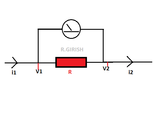
A shunt resistor with very low resistance R and assume some kind analog meter is connected across the resistor who’s deflection is directly proportional to voltage through the analog meter.
Now let’s pass some amount of current from left hand side. i1 is the current before entering the shunt resistor R and i2 will be the current after passing through shunt resistor.
The current i1 will be greater than i2 since it dropped a fraction of current through shunt resistor. The current difference between the shunt resistor develops very small amount of voltage at V1 and V2.
The amount of voltage will be measured by that analog meter.
The voltage developed across the shunt resistor depends on two factors: the current flowing through the shunt resistor and the value of the shunt resistor.
If the current flow is greater through the shunt the voltage developed is more. If the value of the shunt is high the voltage developed across the shunt is more.
The shunt resistor must be very tiny value and it must possess higher wattage rating.
A small value resistor ensures that the load is getting adequate amount of current and voltage for normal operation.
Also the shunt resistor must have higher wattage rating so that it can tolerate the higher temperature while measuring the current. Higher the current through the shunt more the heat is generated.
By now you would have got the basic idea, how an analog meter works. Now let’s move on to digital design.
By now we know that a resistor will produce a voltage if there is a current flow. From the diagram V1 and V2 are the points, where we take the voltage samples to the microcontroller.
Calculating Voltage to Current Conversion
Now let’s see the simple math, how can we convert the produced voltage to current.
The ohm’s law: I = V/R
We know the value of the shunt resistor R and it will be entered in the program.
The voltage produced across the shunt resistor is:
V = V1 – V2
Or
V = V2 – V1 (to avoid negative symbol while measuring and also negative symbol depend on direction of current flow)
So we can simplify the equation,
I = (V1 – V2)/R
Or
I = (V2 - V1)/R
One of the above equations will be entered in the code and we can find the current flow and will be displayed in the LCD.
Now let’s see how to choose the shunt resistor value.
The Arduino has built in 10 bit analog to digital converter (ADC). It can detect from 0 to 5V in 0 to 1024 steps or voltage levels.
So the resolution of this ADC will be 5/1024 = 0.00488 volt or 4.88 millivolt per step.
So 4.88 millivolt/2 mA (minimum resolution of ammeter) = 2.44 or 2.5 ohm resistor.
We can use four 10 ohm, 2 Watt resistor in parallel to get 2.5 ohm which was tested in the prototype.
So, how can we say the maximum measurable range of the proposed ammeter which is 2 Ampere.
The ADC can measure from 0 to 5 V only i.e. . Anything above will damage the ADC in the microcontroller.
From the tested prototype what we have observed that, at the two analog inputs from point V1 and V2; when the current measured value X mA, the analog voltage reads X/2 (in serial monitor).
Say for example, if the ammeter reads 500 mA the analog values on serial monitor reads 250 steps or voltage levels. The ADC can tolerate up to 1024 steps or 5 V maximum, So when the ammeter reads 2000 mA, the serial monitor reads 1000 steps approx. which is near to 1024.
Anything above 1024 voltage level will damage the ADC in Arduino. To avoid this just before 2000 mA a warning message will prompt on LCD saying to disconnect the circuit.
By now you would have understood how the proposed ammeter works.
Now let’s move on to constructional details.
Schematic diagram:
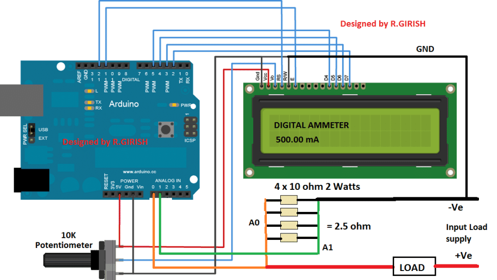
The proposed circuit is very simple and beginner friendly. Construct as per the circuit diagram. Adjust the 10K potentiometer to adjust display contrast.
You can power the Arduino from USB or via DC jack with 9 V batteries. Four 2 watt resistors will dissipate the heat evenly than using one 2.5 ohm resistor with 8- 10 watt resistor.
When no current is passing the display may read some small random value which you may ignore it, this might be due to stray voltage across measuring terminals.
NOTE: Don’t reverse the input load supply polarity.
Program Code:
//------------------Program Developed by R.GIRISH------------------//
#include <LiquidCrystal.h>

#define input_1 A0
#define input_2 A1

LiquidCrystal lcd(12, 11, 5, 4, 3, 2);

int AnalogValue = 0;
int PeakVoltage = 0;
float input_A0 = 0;
float input_A1 = 0;
float output = 0;
const float Resolution = 0.00488;
const int threshold = 1000;
unsigned long sample = 0;

void setup() {
  lcd.begin(16, 2);
  Serial.begin(9600);
}

void loop() {
  // ----- Read Peak Voltage from input_1 -----
  PeakVoltage = 0;
  for (sample = 0; sample < 5000; sample++) {
    AnalogValue = analogRead(input_1);
    if (AnalogValue > PeakVoltage) PeakVoltage = AnalogValue;
    else delayMicroseconds(10);
  }
  input_A0 = PeakVoltage * Resolution;

  // ----- Read Peak Voltage from input_2 -----
  PeakVoltage = 0;
  for (sample = 0; sample < 5000; sample++) {
    AnalogValue = analogRead(input_2);
    if (AnalogValue > PeakVoltage) PeakVoltage = AnalogValue;
    else delayMicroseconds(10);
  }
  input_A1 = PeakVoltage * Resolution;

  // ----- Calculate output in mA -----
  output = (input_A0 - input_A1) * 100;
  output *= 4;

  // ----- Check for maximum limit -----
  while (analogRead(input_1) >= threshold) {
    lcd.clear();
    lcd.setCursor(0, 0);
    lcd.print("Reached Maximum");
    lcd.setCursor(0, 1);
    lcd.print("Limit!!!");
    delay(1000);
    lcd.clear();
    lcd.setCursor(0, 0);
    lcd.print("Disconnect now!!");
    delay(1000);
  }

  // ----- Display output -----
  lcd.clear();
  lcd.setCursor(0, 0);
  lcd.print("DIGITAL AMMETER");
  lcd.setCursor(0, 1);
  lcd.print(output);
  lcd.print(" mA");

  Serial.print("Voltage Level at A0 = ");
  Serial.println(analogRead(input_1));
  Serial.print("Voltage Level at A1 = ");
  Serial.println(analogRead(input_2));
  Serial.println("------------------------------");

  delay(1000);
}
//------------------Program Developed by R.GIRISH------------------//
Code Explanation
Okay so first we have the libraries and pin stuff, you include LiquidCrystal.h so the Arduino can talk to a 16×2 LCD, simple.
Then there is input_1 and input_2 which are just A0 and A1, your analog pins. That lcd(12, 11, 5, 4, 3, 2) line, it is basically hooking the LCD to the Arduino pins, RS, EN, D4, D5, D6, D7, that is all.
Now the variables, we got AnalogValue starts at zero, it stores each reading from the pins. PeakVoltage, also zero at first, keeps track of the highest voltage read during the loop.
Then input_A0 and input_A1, those are just storing the converted voltage in volts for the two pins. Output, that one will be the current you want to display in mA.
Resolution is 0.00488 comes from 5V divided by 1024, just converts ADC counts into volts. Threshold is 1000, the max safe ADC reading, if it goes beyond, code yells at you. Sample is just a counter for loops.
Now the setup() function, we start the LCD with lcd.begin(16, 2), so it knows it is 16×2. And Serial.begin(9600), that opens serial for debugging, like watching numbers fly by in your computer.
Then the main loop(), this runs over and over.
We first read the peak voltage from input_1, so PeakVoltage = 0, then we loop 5000 times, reading input_1 with analogRead(), if the new reading is bigger than PeakVoltage, we replace it or else we just wait a tiny bit, delayMicroseconds(10).
After 5000 times, we take that peak and multiply by Resolution → boom, that is input_A0 in volts.
Same thing for input_2, reset PeakVoltage, loop 5000 times, read input_2, keep the max, then convert with Resolution → now we got input_A1 in volts too.
Then we calculate output, basically output = (input_A0 - input_A1) * 100 and then multiply by 4 again, so in total it is (V1 - V2) * 400, that gives current in mA, matches your circuit calibration, done.
Next, safety check, we keep an eye on input_1, if analogRead(input_1) >= threshold, the LCD starts yelling, clears screen, prints Reached Maximum Limit!!!, then clears and prints Disconnect now!!, keeps repeating until you actually disconnect, just in case.
Then we display the output, clear LCD, first line says DIGITAL AMMETER, second line prints the current in mA. At the same time we print voltage readings for A0 and A1 in Serial Monitor, then pause a second with delay(1000) before looping again.
So basically it is measuring peak voltages from two analog inputs, calculates the current difference, shows it on the LCD and serial monitor, and if voltage is too high, it warns you loud enough.
If you have any specific question regarding this Arduino based digital ammeter circuit project, please express in the comment section, you may receive a quick reply.

Comments
Can this circuit read both AC and DC mA?
DC mA. AC mA can be also read if a bridge rectifier is configured with the load.
Hi Swag,
i try to build this Circuit and upload the Code to Arduino Uno but aim getting following fonts only on my lcd
ññññññññññññññññ
ññññññññññññññññ
and aim using LCD keyboard Shield on arduino uno. (arduinolearning.com/wp-content/uploads/2014/12/lcd-keypad-shield.jpg)
Dear bro,
Please help me to build 4 channel voltmeter using aurdrino uno board with LCD 16 x2 ( direct measurement auto ranging 0 to 50v DC without any selector switch I.e 0-5v and 5-50v )
Thank you
(Deepak)
Hi Deepak, the idea is already present in many online websites, please search “4 channel Arduino voltmeter” you will be able to find quite a few of them.
This is an amazing tutorial. Is there a way I could measure smaller currents; in the micro-Ampere range?
Hi Nicole,
Thanks,
No you can’t measures in micro-amps with this circuit because arduino has limited ADC resolution.
There could be external modules which can help you measure in micro amps.
Regards
There are no branches for the current in the shunt circuit shown. There is only one current which is flowing through the shunt resistor. Hence, I1 and I2 are same. Please correct the posting. Anyway, the current flowing through the shunt is V1-V2/R where R is shunt resistor. The arduino sketch is correct.
The posting is probably written by considering the fact that if the current is checked across I1 and ground with an ammeter and then across I2 and ground we will find a difference in current where I2 reading will be less than I1.
I2 = V /shunt R
Thanks for your articles. I enjoy them very much. I have one small correction for this one, however. Kirchhoff’s current law (KCL) tells us that I1 must equal I2.
Regards,
Thanks Richard, however I am sorry it seems you have misinterpreted the law, according to Kirchoff’s current law the algebraic sum of the currents at a junction point in a circuit network is always zero…therefore i1 and i2 will be definitely different but there algebraic sum will be zero satisfying the law…I hope it makes sense!