In this post I have explained a method to harvest free electricity from a piezo embedded mat by walking on it, and try to investigate how this energy may be used for charging a small battery.
Normally a human body carries a huge amount of energy which simply gets wasted in our regular day to day work. For example energy in the form of heat from our body and head surface, energy through our every movement while we sit and work, sleep etc.
However the largest amount of energy that's simply wasted is while walking.Here we will see how the our walking process can be utilized for generating electricity using piezo devices.In one of my earlier articles I posted a similar topic which explained how to generate electricity from shoes using a solenoid, here we will study how a piezo may be used for harvesting electricity from our footsteps, although this concept could be much weaker with its specs and therefore much inefficient with the performance compared to its solenoid counterpart.
Before we begin applying a piezo for our foot step activated free energy generator circuit, it would be interesting to know how much maximum power can a piezo actually generate when an optimized amount of pressure is struck on it.
If we analyze a standard 27mm buzzer piezo,, we find that when it's struck or hit sharply (without damaging) it is able to generate around 1 to 3V DC, which may be capable of illuminating a 5mm LED brightly. Well that looks impressive however striking the right kind of force at the right speed and over the right spot is something that looks difficult to execute. Still it may be feasible to make these devices work for the intended purpose reasonably well, with some planned effort.
AS discussed above a piezo element may be capable of generating upto 3V, but the current (amp) may be quite less at around 10 to 20mA, therefore for operating a relatively larger load such as charging a battery this current might not be enough and we may require many number of piezo elements to work together in order to produce a higher amount of current from them.
How to connect multiple piezos together to increase current
In order to increase the amount of current from a piezo mat generator circuit, it becomes imperative to join them in parallel, since parallel connection causes current addition while series connection allows voltage addition.
To implement this each piezo must include its own separate bridge rectifier unit, as shown in the following figure:
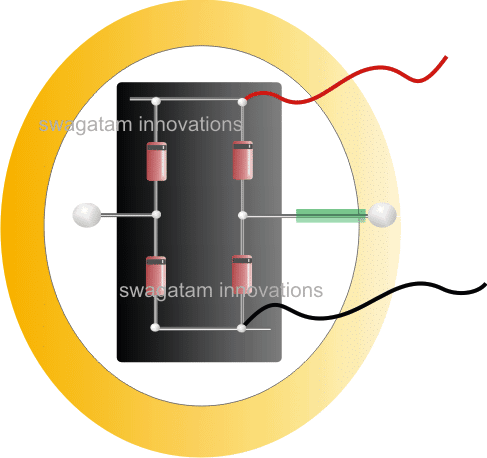
The picture shows a 27mm two terminal piezo at the base, the golden colored area represents the metal plate of the piezo while the white circle represents the central piezo material laid down on the golden plate.
Over the white portion of the piezo we can see a black insulation tape stuck to provide an insulated resting platform for the bridge rectifier which is made up of 4 x BAS86 Schottky diodes (shown red color).
The bridge is firmly assembled on the above mentioned surface with pieces of copper wires, we can see two of them terminating from the central junctions of the bridge rectifier, one soldered on golden plate of the piezo while the other soldered on the central white piezo material (be careful while soldering on the white surface as it's quite delicate and may easily get stripped of).
The positive and the negative ends of the bridge is terminated using red/black wires, and these wires from each of the piezo/bridge assembly needs to connected together. Meaning suppose we have 50 such piezo assemblies, then all the red wires from the 50 assemblies should be joint together, and the 50 black wires joined together.
These common negative/positive joints then may be connected to a higher value electrolytic capacitor., and further on to the (+)(-) battery terminals (for charging).
The diodes may be additionally secured by applying a few drops of super glue on each of the diodes.
You can also opt for SMD diodes in order to make the bridge extremely compact and light weight.
This concludes the piezo bridge assembly which explains how to connect the piezos in parallel for multiplying current output, now let's move ahead and learn the best possible method of configuring the above assembly with a mechanism that would most effectively convert foot steps into electricity from the piezos.
Piezo Mat Electricity Generator Mechanism
As I have explained through our earlier studies, a piezo might not generate electricity effectively unless it's struck or hit with some kind of force or jerk, to be precise the striking should be snappy, in order to produce the maximum from these devices.
That implies soft pressing of a piezo will not be sufficient to drive these devices optimally meaning just by pressing the piezo assembly with your feet will not help to generate significantly from them.
Remember piezo is different from a load cell.
The piezo mat should be equipped with a mechanism that must be capable of converting even a slow foot step into a snappy strike over the piezos.
Upon some thinking I devised the following method of implementing a piezo mat that would be hopefully able to achieve maximum from the devices. If you have a better solution you can feel free to use it instead of this.
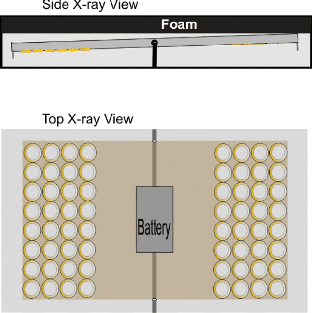
The diagram below shows the mechanism consisting of a wooden plank pivoted at the center, and covered with a layer of foam or sponge. Whenever somebody steps over the foam, the plank tilts with a "thud" causing a significant amount vibration on the entire plank. The same repeats when the foot step is lifted of the system.
Piezo Positioning
The piezo assembly positioning can be witnessed in the above figure.
The grey area is the Mat base, the yellowish section signifies the wooden plank having a central pivotal rod so that it can smoothly flip-flop across either sides whenever a person steps on it.
The piezo assemblies discussed above can be fixed at the lower surface of the plank towards the edge for enabling maximum impact on them. The edge of the Plank will produce the maximum impact than the central pivotal section, therefore it's advisable to move the piezos as close as possible to the edge of the plank.
Sticking the Piezos will Require Special Care
You cannot simply stick the piezos directly on the indicated plank, because doing so would simply dampen the piezo movement making them quite inefficient.
The right method would be to punch undersized holes and stick the piezos across them such that only the rim of the piezos are able to make contact with the plank while their central portion hang in the gap of the holes, as shown below
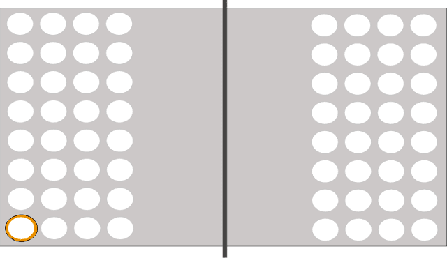
As may be seen in the above design, the plank is punched with holes corresponding to the number of piezos that needs to be stuck, one piezo can be seen fixed from under the plank such that only its golden border makes contact with the plank while the remaining central section stays aloof within the hole gap.
This method of sticking ensures the most effective vibrational impact on the piezos whenever its hit with somebody's footstep.
Enhancing the Footstep Force on the piezo mat generator
In the above section I have explained the technique of a pivoted plank loaded with the piezos for enforcing a flip flop kind of movement in response to the footsteps, so that the plank causes maximum vibrational impact on the piezos.
The process could be enhanced even further by adding a magnet across each ends of the plank, as shown below:
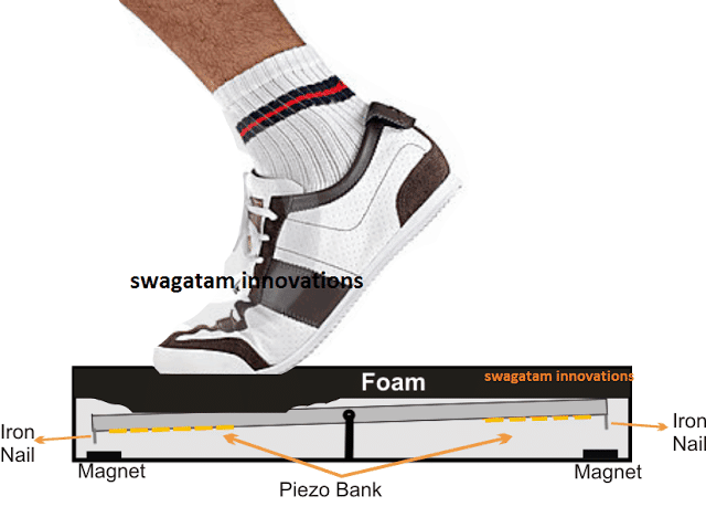
As we can see, an iron nail is inserted at the lower edge of the plank and a magnet placed on the bottom base parallel to the nail, such that whenever the plank tends to tilt due to a foot stepping, the magnet pulls the edge more quickly towards the tilted side causing an enhanced "knocking" impact on the relevant side, which in turn causes an equivalent amount more vibrational stress on the respective piezo assembly, ensuring a higher electricity generation from them.


Questions & Answers
“Free energy” Yeah right.
Well at least this one will actually work, generating a small amount of power.
Now put it in the soles of your shoes to charge your phone.
Could you recommend other diodes? I didn’t find these for sale here in Brazil
Do you have a website for piezo electric tiles . And where to order including installation Sir.
Thankyou very Much.
1N4148 are the most commonly available diodes….there’s no easy replacement for this.
Sir,
if you put 5 piezoelectric plates in series and then put the diode bridge, you could reach a voltage of 5v to 15v at the output of the diode bridge?
And if I put these bridges of each 5 piezoelectric plates in parallel, would I be able to increase the voltage?
It may be possible if all the piezos AC outputs are in phase with each other, which is usually not possible, that is why I have used separate bridges for each piezo.
Thanks, for all your information. I’m an electronics from way back. Really do appreciate all you do.
Walt.
Thanks for sharing your thoughts, please keep up the god work!
Hello Sir,
Like to know, as you mentioned with each piezo disc 1 rectifier to be attached,
“To implement this each piezo must include its own separate bridge rectifier unit, as shown in the following figure:”
1. What if we attached all piezo disc in Parallel & connect single Bridge Rectifier at the end, what difference it makes &
2. Also a bridge rectifier requires around 1.4V (0.7V * 2) as forward Voltage, So with Individual Bridge Rectifier, will it be feasible to get more than 1.4V with each Piezo Disc (own separate bridge rectifier unit).
Thanks in Advance,
Ashish
Hello Ashish,
piezos in parallel will not generate same amount of electricity and may also generate electricity with opposite polarity, which can cancel out the voltages across the piezos affecting the overall the power output, that is why bridge for every piezo is recommended.
A piezo is able to generate as high a 4V when struck adequately, so a drop of 1.4V is manageable, although a schottky diode can be also tried to minimize the drop…. or a BJT based rectifier can also be applied for the same…the available difference can be amplified using a joule thief kind of circuit
sir i think placing the piezo directly under the foam will give max output, as per my expicrnc the more the force on the disc the more is the output. where as the vibration will not make much difference.
also what are sepcificatin of the battery should be used and do we need any more ckt to store the energy in the battery or we can directly connect the capacitor to the battery
and yes thank you very much for ur reponse 🙂
you can directly connect the battery with the output…initially you can try a cheap chinese make 3V battery pack which are used in mosquito swatter bats….
and sir what about the battery specifications? do we need another ckt or we simply need to connect the capacitor to the battery
lekhraj, pressing the piezo will yield nothing, piezos require a striking with sudden force for generating maximum electricity from them…..you can try it, you will know.
also bending a piezo can also help in producing electricity, but that can break and damage the device permanently.
Need a circuit of stereo FM transmitter with a 500m range. It will be great if the coil is in the PCB