• Skip to main content
  • Skip to primary sidebar

Homemade Circuit Projects

Need circuit help? Post them in the comments! I've answered over 50,000!

Blog | Categories | About | Contact | Calculators-online
You are here: Home / Health related Projects / Sleeping Aid Circuit

Sleeping Aid Circuit

Last Updated on August 30, 2023 by Swagatam 12 Comments

The sleep aid circuit appears to be particularly effective when used with young children experiencing restless nights. This can, in turn, contribute to the entire household enjoying uninterrupted sleep.

Table of Contents
  • What is a Sleeping Aid Circuit
  • Circuit Description

With the sleep aid device operating next to you, you can customize the volume and depth settings according to your mood. Then, recline and focus your attention on the sound.

Over time, the sound will begin to have an almost hypnotic effect – continuously changing, yet consistently the same.

Before long, you will find yourself being carried away by the waves of sound until there's no option but to gently drift into a profound and soothing slumber.

What is a Sleeping Aid Circuit

A sleep aid circuit is an electronic circuit which helps the user to sleep better. It generates soothing sound effects through white noise.

This noise is random audio signal consisting of frequencies within all ranges audible to humans. This continuous and consistent generation of sound can mask other background noises and create a calming environment.

This is in turn can help promoting relaxation and improving sleep quality for the user.

The circuit normally works with a zener diode noise generator stage and an amplifier to produce the white noise and transmit it through a loud speakers

Circuit Description

sleeping aid circuit

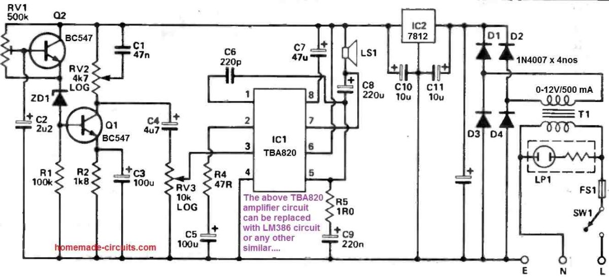
Describing the circuit diagram, the sleeping aid device enables the adjustment of both sound volume and depth. It also facilitates circuit tuning to achieve optimal output.

RV1 establishes operational parameters for ZD1, enabling it to generate maximum output.

Q1 significantly boosts the output, while RV2 fine-tunes the sharpness of the high-frequency cutoff. IC1 enhances the sound signal and propels it through the speaker.

The voltage amplification of IC1 is determined by R4. C6 moderates the amplifier's gain at higher frequencies to maintain stability.

R5 and C9 alter the load on the amplifier, giving it a more resistive characteristic at higher frequencies. This modification aids in transient response and overall stability.

IC2 functions as a voltage regulator, ensuring a consistent 12V power supply for the circuit.

You'll also like:

  • 1.  4 Universal Electronic Thermometer Circuits
  • 2.  Bluetooth Stethoscope Circuit
  • 3.  Ultraviolet (UV) Sanitizer Circuit for Disinfecting Home Materials
  • 4.  Red LED LightStim Circuit for Removing Facial Wrinkles
  • 5.  Digital Thermometer Circuit – Uses a Solar Cell for Power
  • 6.  Electronic Acupuncture Circuit [Bio-Stimulation Circuit]

About Swagatam

I am an electronics engineer with over 15 years of hands-on experience. I am passionate about inventing, designing electronic circuits and PCBs, and helping hobbyists bring their projects to life. That is why I founded homemade-circuits.com, a website where I share innovative circuit ideas and tutorials. Have a circuit related question? Leave a comment.... I guarantee a reply!

Previous Post: « Simple Ceiling Fan Regulator Circuit
Next Post: Ding Dong Bell Circuit that Saves Electricity »

Reader Interactions

Comments

  1. Jan says

    May 20, 2024 at 9:58 pm

    Hi Swagtam.
    Is the 220nf value of C9(Electrolytic Cap) correct?
    Regards
    Jan

    Reply
    • Swagatam says

      May 20, 2024 at 10:19 pm

      Hi Jan, in the diagram C9 is 220 nF…

      Reply
      • Swagatam says

        May 20, 2024 at 10:24 pm

        Hi Jan, you may have to refer to the IC datasheet to confirm whether the value is correct or not, or if in doubt you can simply replace the amplifier section with an LM386 amplifier circuit…or any other amplifier as per your preference…

        Reply
  2. Jan says

    April 4, 2024 at 1:28 pm

    Hi Swagatm,
    I have build this circuit but unfortunately I can not get the Zener diode to oscillate. PIN 3 of IC1 gets no signal. I have done fault finding with my scope. Everything seems to work OK, except for the Zener.
    Your advice will be much appreciated.
    Regards
    Jan

    Reply
    • Swagatam says

      April 4, 2024 at 5:02 pm

      Hi Jan,
      It can be difficult for me to check why the zener is not generating the noise in your circuit.
      You can do one thing, use any “White noise generator” circuit and integrate its output with the potentiometer of the amplifier circuit.
      You can try one of these white noise generators or any other available online.:

      https://www.homemade-circuits.com/white-noise-and-pink-noise-generator-circuit/

      Reply
      • Jan says

        April 4, 2024 at 5:22 pm

        Thank you Swagatam I will certainly do that.

        Reply
        • Swagatam says

          April 4, 2024 at 8:09 pm

          You are welcome Jan…

          Reply
  3. Franklin Miguel says

    October 21, 2023 at 7:16 pm

    Buenos días Sr. Gracias por publicar sus proyectos.
    En el diagrama, el diodo zener no indica su voltaje de trabajo me puede decir?

    Reply
    • Swagatam says

      October 21, 2023 at 8:11 pm

      Thank you Franklin, you can use any zener diode between 3 V and 6 V.

      Reply
  4. rosario says

    September 3, 2023 at 10:43 pm

    Goodmorning Sir. I noticed that in the diagram the capacitor after the diodes D1 and D3 has no value. Can you please give it?

    Reply
    • Swagatam says

      September 4, 2023 at 7:52 am

      Goodmorning Rosario, that capacitor is a simple filter capacitor, which can have any value between 1000uF/25V and 2200uF/25V

      Reply
      • rosario says

        September 17, 2023 at 4:07 pm

        Thanks

        Reply

Need Help? Please Leave a Comment! We value your input—Kindly keep it relevant to the above topic! Cancel reply

Your email address will not be published. Required fields are marked *

Primary Sidebar

Subscribe to New Circuit Ideas

Categories

  • Arduino Projects (87)
  • Audio and Amplifier Projects (132)
  • Automation Projects (17)
  • Automobile Electronics (101)
  • Battery Charger Circuits (83)
  • Datasheets and Components (104)
  • Electronics Theory (143)
  • Free Energy (37)
  • Games and Sports Projects (11)
  • Grid and 3-Phase (19)
  • Health related Projects (25)
  • Home Electrical Circuits (12)
  • Indicator Circuits (14)
  • Inverter Circuits (87)
  • Lamps and Lights (142)
  • Meters and Testers (69)
  • Mini Projects (46)
  • Motor Controller (64)
  • Oscillator Circuits (27)
  • Pets and Pests (15)
  • Power Supply Circuits (108)
  • Remote Control Circuits (50)
  • Security and Alarm (64)
  • Sensors and Detectors (101)
  • Solar Controller Circuits (59)
  • Temperature Controllers (42)
  • Timer and Delay Relay (49)
  • Transmitter Circuits (29)
  • Voltage Control and Protection (37)
  • Water Controller (36)

Calculators

  • Battery Back up Time Calculator
  • Capacitance Reactance Calculator
  • IC 555 Astable Calculator
  • IC 555 Monostable Calculator
  • Inductance Calculator
  • LC Resonance Calculator
  • LM317, LM338, LM396 Calculator
  • Ohm’s Law Calculator
  • Phase Angle Phase Shift Calculator
  • Power Factor (PF) Calculator
  • Reactance Calculator
  • Transistor Astable Calculator
  • Transistor base Resistor Calculator
  • Voltage Divider Calculator
  • Wire Current Calculator
  • Zener Diode Calculator
  • Filter Capacitor Calculator
  • Buck Converter Calculator
  • Boost Converter Calculator
  • Solar Panel, Inverter, Battery Calculator
  • Wire Current Calculator
  • SMPS Transformer Calculator
  • IC SG3525, SG3524 Calculator
  • Inverter LC Filter Calculator

People Also Search

555 Circuits | 741 Circuits | LM324 Circuits | LM338 Circuits | 4017 Circuits | Ultrasonic Projects | SMPS Projects | Christmas Projects | MOSFETs | Radio Circuits | Laser Circuits | PIR Projects |

Recent Comments

  • Swagatam on Battery Deep Discharge Protection Circuit
  • Swagatam on 10 LED Tachometer Circuit Diagram
  • Drew Adare on How to Collect Free Energy from Atmosphere
  • Göran on 10 LED Tachometer Circuit Diagram
  • Abdulmajid Haruna on Laptop Power Bank Circuit

Company

  • Privacy Policy
  • Cookie Policy
  • About Me
  • Contact
  • Disclaimer
  • Copyright
  • Videos
  • Sitemap

Social Profiles

  • Twitter
  • YouTube
  • Instagram
  • Pinterest
  • My Facebook-Page
  • Quora
  • Stack Exchange
  • Linkedin
  • © 2025 · Swagatam Innovations