In this post I have explained a simple water level controller circuit applicable for automatic toggling of two submersible water pumps alternately in response to a predetermined water level switching. The entire circuit is built using just a single IC and a few other passive parts. The idea was requested by one of the interested members of this blog.
Technical Specifications
Can you help me with this problem: In a basement sump, there are two submersible pumps with float switches (P1 and P2) installed to achieve some level of redundancy.
In order to use both pumps equally, we want to alternate between P1 and P2 whenever a preset water level is reached. That is, the first time the preset level is reached P1 should start and pump the water out. Next time when the preset level is reached P2 should start and pump the water out.
On next occasion it will be P1's turn and so forth. What we need is an "alternating" relay control running P1 and P2 turn by turn.
The Design
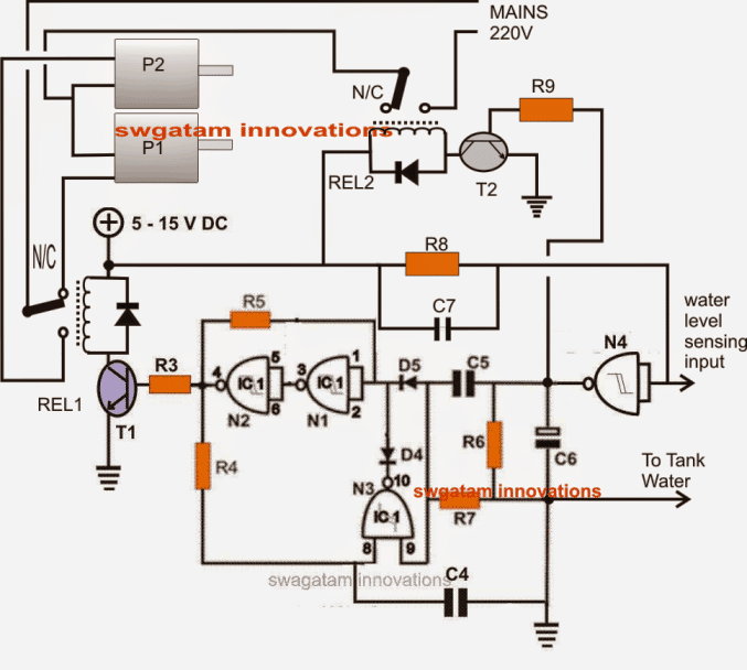
The shown circuit of an automatic submersible pump controller can be understood as given under:
As can be seen the entire circuit is built around four NAND gates from a single IC 4093.
The gates N1--N3 form a standard flip flop circuit wherein the output of N2 toggles from high to low and vice versa in response to every positive trigger at the junction of C5/R6.
N4 is positioned as a buffer whose input is terminated as the sensing input for detecting the presence of water over a predetermined fixed level inside the tank.
The link from the ground or the negative of the circuit is also stationed into the tank water close and parallel to the above sensing input of N4.
Initially assuming no water in the tank keeps the input of N4 at high via R8, resulting in a low output at the junction of C5/R6.
This renders N1, N2, N3 and the entire configuration in a unresponsive standby position, resulting in T1, T2 being in a switched OFF position.
This holds the respective relays REL1/2 in an deactivated position with their contacts at N/C levels.
Here REL2 contacts make sure that the supply voltage stays cut off during the absence of water in the tank.
Now suppose water in the tank starts rising and bridges the ground with N4 input rendering it low, this prompts a high signal at the output of N4.
This high at the output of N4 activates T2, REL2 and also flips the output of N2 such that REL1 also gets activated. Now REL2 allows the mains voltage to reach the motors.
And with REL1 also activated actuates the pump P2 via its N/O contacts.
As soon as the water level sinks below the preset point reverts the situation at the input of N4, creating a low a its output.
However this low signal from N4 produces no effect on REL1 as N1, N2, N3 hold REL1 in the activated position.
REL2 being directly dependent on N4 output switches OFF cutting off mains supply to the motors and switching P2 OFF.
During the next cycle when water level reaches the sensing points, N4 output toggles REL2 as usual allowing mains supply to reach the motors, and also switches REL1 but this time toward is N/C contact.
This instantly flips P1 into operation because P1 is configured with the N/C of REL1 thus resting P2 and actuating P1 on this occasion.
The above alternate flipping of P1/P2 keeps repeating with the ongoing cycles as per the above operations.
Circuit Diagram
Parts list for the above automatic submersible pump controller circuit:
- R3, R9 = 10K,
- R4, R5, R8 = 2M2,
- R6, R7 = 39K,
- R4, R5 = 0.22, DISC,
- C6 = 100µF/25V,
- D4, D5 = 1N4148,
- C4, C5, C7 = 0.22uF
- T1, T2 = BC 547,
- N1---N4 = IC4093,
- Relays = 12V, SPDT, 20 amp contactsrelay dides = 1N4007

Questions & Answers
can you design a iot based circuit which will be activated by float switches and would control a submersible pump. It will also allow control of water pump by mobile
Sorry, I’m not very good with IoT concepts, so designing it can be hard for me.
Dear Jorge, I’ll publish the design soon in my blog, and let you know once it is posted
Awesome Sir. Thanks and I look forward to hearing from you.
Hi Jorge, I have published the required circuit design in the following post:
https://www.homemade-circuits.com/pressure-switch-water-pump-controller-circuit/
hello sir, i have a water reserver tank and an upperhead tank, how can i control the water level of this two tank. please sir help me. give any circuit diagram.
Hello Rakesh, you can build this and connect it with the lower tank, it will take care of the situation:
https://www.homemade-circuits.com/how-to-make-simple-water-level/
for the upper tank also you may have build another such unit
Sir,Kindly give a ckt of water-pump controller for single phase 1-2 HP Submersible pumps.
I think I already have a couple of submersible pump controller circuits in this website, please use the search box to find it out.
Dear Swagatam,
can you design a timer circuit which switches on the relay just 2 sec and then goes off. This can be used to activate the charge capacitor of Submersible pump panel.
Dear Chandan, just add a capacitor in series with a resistor to the base of the relay driver transistor, and you will find it executing the required function.
the value of the capacitor will determine the delay response.
Hi Dear Swagatam,
I want to make water level controller using Flot switch.
purpose is i have submersible pump and overhead tank, so i think to make circuit for to start pump when overhead tank empty and stop pump when over head tank full. and i show some circuit using ic555 but their contact(probe) is directly connected with water so i don't want to contact any voltage to connect in water so using flot switch is good option.
sorry for long story but i beleve Safety first.
Dear Jadoo,
you would first need to make a float switch and then it could be attached with a good relevant water level controller circuit module.
I would be discussing the concept soon in this blog.
There's already one post in this blog using a float switch, however the design is not fully automatic, you can refer to it here:
https://www.homemade-circuits.com/2014/04/float-switch-water-level-controller.html
hi sir i have the same problem as connecting the relay to the existing submersible starter. the starter has 1 capacitor for start and one capacitor for run and a 15amps magnetic contactor with push to on switch and push to off switch.in my water level controller circuit i have only one relay to used to on and off the pump. the circuit works well for a jet pump which has 15amps on off switch but how to connect it to a submersible pump starter panel.please help me to connect it.
Hi Arindam, you will have to make and check the stages separately then integrate them together.
You can begin first with the water level controller circuit given in the following link, once you complete this successfully we can proceed with the remaining stages:
https://www.homemade-circuits.com/2011/12/how-to-make-simple-water-level.html
Hi sir i want a automatic water level controller cum motor protector based on submersible pump.when overhead tank empty up to certain level the pump must automatically start and when its filled up to certain level pump must stop.i need over and under voltage protection and if dry run condition or overload(excessive current drawing) condition happen pump must stop with an alarm.manual on-off switch and total bypass of this circuit is very essential.
Hi Arindam, the circuit is too lengthy and could be quite time-consuming for me to follow the entire design.
you can tell me briefly what exactly you require, probably I may be having it in this blog or will try to guide you appropriately with a new design…but not with a pic
hi sir i already sent you the pdf file.please modify or redesigned it for me with over under voltage protection and if dry runing happen then with audio sound the motor should stop.if it can be pic16f84a based then it will be very good for me.
hi Arindam, my email IDs are given in the "contact" page on top
hi sir i have a circuit for submersible pump starter from efy. how can i send it to you? if you observe this circuit and make a simplified version with ic then it will be very good.if u give your mail id then i will send you the pdf file so u can study it and make some changes.
I think the start switch operation is crucial..it momentarily connects the start winding of the motor with the AC supply and removes it once te button is released, this operation is essential for initiating the motor rotation….this has to be implemented manually no matter with what device the motor is hooked up with.
This may be true even for the above circuit.
But this can be very undesirable for the user so probably some automatic alternative must be thought of and could become handy in conjunction with the above circuit….will try to include it soon.
i cant figure out is there a centrifugal switch connected because the whole pump and motor is submerged in water.it is only the starter panel i can play with.in the panel there is a green push button switch which you have to press for 2 second this will activate the magnetic contactor.. from this contactor switch a white plastic shaft is connected through push to off switch, when u press the off switch the red one this plastic shaft is goes down and the pump stop.the panel has a voltmeter and amp meter.
Hi Arindam, do you have a centrifugal switch connected with the pump motor??
Dear sir,
There is a problem in push button switch..it has a start capacitor which has to be used at the start and then to be cut off..so how can I do it..is there any idea with the circuit..please help me
Regards
Karthick
Hai sir,
Thanks for ur reply,let me draw and send it to u shortly ..
Thanks
Karthick
Dear Karthick,
I would require the complete wiring diagram of the system, then i could try to figure out an electronic version of it, so you can probably draw the connection diagram and send it to my email.
Hai sir,
I need a circuit which automates the push buttons of the starter provided for the submersible pumps..because the power supply cannot be given directly to the pump..is there anything that u could help me out..
Many thanks
Karthick
Hai sir,
I've tried many of ur circuits and u r doing great..I have a problem in my home borewell submersible pump and I hope u would help me out with this..there is a starter for my pump and it has a push to on and push to off switches..so I don't know how to direct the mains supply to the pump as the starter is compulsory for the pump to start..is there any circuit that could automate the push buttons.
Hi Karthick,
you can replace the starter switches with equivalent power relays.
The relay coils would need 12V or 24V DC for operating through mains, this could be supplied via AC/DC adapter, and the relay contacts then can be wired with the motor via AC mains for the required switching
You are welcome!
I could not find a mechanical bistable (latching) type relay, if it's available then N1,N2,N3 circuit will not be required, the relay can be replaced with REL1 and T1 base directly integrated with the output of N4.
you can try the circuit given in the following article, you will need to tweak the coil turns a bit for getting the preferred voltage level
https://www.homemade-circuits.com/2013/08/15v-to-12v-dc-converter-circuit-for.html