This easy yet useful security alarm circuit is designed to get triggered in response to even a brief movement of the unit, causing a loud alarm sound to set off.
The circuit could be attached or installed on any desired gadget or asset which needs to be protected from theft. As soon as the gadget is displaced or moved with an intention to steal, the device alarm will sound

How the Sensor Works
You can find a variety of sensors that could be tried for S1, however a mercury switch could be the apparent type to go with.

A mercury switch is essentially just a couple of electrodes sealed inside an insulated tube and moderately stuffed with mercury.
In this sensor, a change in its position causes the mercury to shift its contact from the electrodes so that the electrodes are left open.
However, with some other orientation, causes the mercury to roll over and come in contact both the electrodes generating a short between the two electrodes.
In an implementation of this type the sensor switch must be arranged so that it is merely a point away where it just creates an electrical contact across the electrodes, so that any kind of small displacement or vibration even for a brief second triggers the switch and sets off the alarm circuit.
Essentially, the circuit only has to create a latching function in response to a brief triggering from the tilt sensor, which is subsequently used to drive an associated alarm device.
In case the unit is required to be powered from a battery, it becomes essential for the circuit to work with minimal stand-by current in order that the unit can remain unattended for long time periods without depleting the battery too much.
A Simple Circuit using a Single Transistor
Before I have explained the main circuit using IC 555, it is important to know that a tilt sensor based anti-theft alarm can be simply built using just a single transistor and a few other parts as shown below:
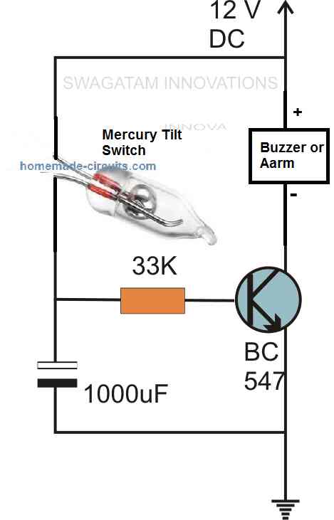
The working is again very simple. The mercury tilt sensor is positioned such that the mercury is slightly away from its contacts. After the circuit is installed inside the valuable item which needs to be protected, the circuit is all set to go.
As soon as a vibration or a tilt is detected which can happen only if somebody tries to steal the item, the mercury is shaken inside the sensor causing a short circuit inside the sensor. This causes the positive supply to connect with the transistor base, The transistor now conducts and sounds the alarm.
The alarm keeps sounding for some time due to the charge inside the 1000uF capacitor even if the tilt sensor is corrected and the mercury is moved away from the contacts.
Now I have explained the next circuit which is a much elaborate and a complex design but nevertheless will perform the anti-theft alarm function vert effectively.
Using IC 555
In this particular security gadget alarm circuit, as shown in the following diagram, the latching action is implemented through a standard set/reset flip/flop created around IC1a and IC1b.

The additional a couple of NOR gates of IC1 are kept unconnected, although their inputs are linked with the negative supply line to ensure protection against static charges, as well as guarantee that the unused gates do not cause any major current usage.
C2 generates the starting 'reset' pulse, to enable the flip/flop stage on the appropriate output condition during the switch-on period, while S1 is poitioned as the mercury switch that enables the output into the high state as soon as it is turned on.
The latch output drives the alarm generator circuit through emitter follower TR1. The alarm generator circuit is created using a pair of 555 IC astable circuits where IC3 is configured for producing the audio tone while IC2 does the job of frequency modulation.
The modulation function is implemented by lightly associating the IC2 output with the control input of IC3 through R8. This configuration allows a straightforward yet powerful two tone 'warbling' alarm noise.
LS1 is an enclosed ceramic resonator that provides large efficiency along with a ear piercing shrill audio output. In case the best possible volume level is intended, R7 could be substituted with a 1M preset which could be tweaked to the spot where the two frequencies offer the highest output.
Applications
This multipurpose anti-theft movement detector alarm circuit could be applied in many different ways. It can be employed like a burglar alarm, attached to a doorway so that the device can be activated as soon as a person moves open the door.
This door could be the entrance of a car or a mobile home and not specifically that of a house. The fully furnished and ideal characteristics of the alarm additionally enables it to be well suited to applications like a travel suitcase or tv set alarm, laptops, in which the alarm could be initialized the moment somebody attempts to take away the secured item.
The anti-theft device can be built very stream-lined, allowing it to be ideally suitable as a security device for pretty much everything precious that cannot be practically bolted down.
Part List


Questions & Answers
Hello, how i do the reset? I mean when the sensor triggered the alarm speaker , how to turned it off? without disconnecting the battery
thanks
Hi, Are you referring to the 555 circuit? You will have to deactivate the tilt switch or switch OFF power to stop the alarm. There’s no other way to reset.
Hi good day could you design the above project alarm circuit board for me and the costs
Hi Chris, sorry assembling a prototype may not be possible for me at this moment.
awesome than..
Like always..awesome circuit mr swag..however can you make it very small? Maybe powered by small watch battery?
Keep inspiring..cheers
Thanks MpQ for liking the concept! It can be made very small and powered with a watch battery if SMD parts are used.
Gracias por tu proyecto me gustan tus vídeos y estoy suscrito a tu canal me gustó tu proyecto de a larma para ver si la puedo a ser para mí moto. Pero no encontré el plano para Acer el circuito.. pero gracias por tu gran talento y sabiduría gracias a Dios eres un genio
Thank you, and glad you liked the projects published in this blog. Appreciate your feedback.