• Skip to main content
  • Skip to primary sidebar

Homemade Circuit Projects

Get free circuit help 24/7

Circuits for Beginners | Basic Circuits | LED Driver | Hobby Circuits | Transistor Circuits

New-Projects | Privacy Policy | About us | Contact | Disclaimer | Copyright

Home » 555 IC Circuits » Power Switch ON Alarm with Auto OFF Circuit

Power Switch ON Alarm with Auto OFF Circuit

Last Updated on July 6, 2019 by Swagatam 15 Comments

The post discusses a simple monostable based power switch ON alarm circuit which automatically switches OFF after an adjustable preset delay. The idea was requested by Mr. Will Boswell.

Technical Specifications

Hi there, my name is Will Boswell. I am currently working on a project that involves adding an alarm sounder to an existing circuit, I shall try and explain as best possible.

The existing system is a warning light system whereby when the high voltage kit that I use is turned on, red beacon lights flash in order to warn those inside and outside of the testing area. These lights operate at 24V.

I would like to put a sounder in that sounds for 5 - 10 seconds when the system is turned on, in addition to the lights.

I was rather hoping that I would be able to just piggyback off of one of these lights for my supply but after my own research I have begun to get rather lost and it is a few years since I was at college!

So in a short summary, I am looking for some assistance in regards to having an alarm sound for 5 - 10 seconds every time the system is turned on / lights are activate.

Please any questions, just ask!

Many Thanks in advance

The Design

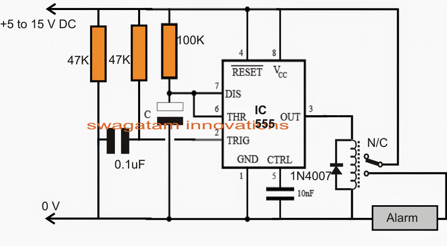
The requested power switch ON alarm circuit using a delay OFF circuit may be witnessed in the given diagram.

It's basically built around a standard IC 555 monostable multivibrator configuration. The operations are rather simple:

When power is switched on across the circuit, the 0.1uF capacitor momentarily grounds pin2 of the IC, sending an instantaneous triggering signal to the 555 monostable.

This immediately prompts the output of the IC to go high causing a toggling voltage to be activated for the attached relay.

The relay switches ON itself and the alarm unit connected with its N/O and the pole.

The alarm begins buzzing only until the relay shuts off automatically due to the featured monostable one shot characteristic of the IC 555.

The ON period of the relay or the IC output is determined by the values of the 100kresistor and caapcitor C. Different values for C may be tried in between 10uF and 100uF for achieving the closest possible duration of 5 to 10 seconds.

Circuit Diagram


You'll also like:

  • 1.  Flashing LED Battery Low Indicator Circuit
  • 2.  Detecting Static Human with PIR
  • 3.  IC 555 Based Simple Digital Stopwatch Circuit
  • 4.  Class D Amplifier Circuit Using IC 555
  • 5.  Quadcopter Remote Control Circuit without MCU
  • 6.  Material Storage Level Controller Circuit

About Swagatam

I am an electronic engineer (dipIETE ), hobbyist, inventor, schematic/PCB designer, manufacturer. I am also the founder of the website: https://www.homemade-circuits.com/, where I love sharing my innovative circuit ideas and tutorials.
If you have any circuit related query, you may interact through comments, I'll be most happy to help!

Subscribe2


Reader Interactions

Comments

    Your Comments are too Valuable! But please see that they are related to the above article, and are not off-topic! Cancel reply

    Your email address will not be published. Required fields are marked *

  1. suresh aprs says

    Sir,
    Im using three phase motor, some time one phase fail. I want three phase preventer with time delay out put and phase revers , low voltage, high voltage detector. Please help me.
    Mail ID: aprssuresh@gmail.com

    Regards
    Suresh

    Reply
    • Swagatam says

      Suresh, you can try the following circuit which is a single phase preventer circuit only, without high, low cut off….make this first if it works as per the requirement, we can later on add the high/low cut off in it.

      easy-electronic-circuits.blogspot.in/2013/08/simplest-single-phase-preventor-circuit.html

      Reply
  2. suresh aprs says

    Thanks for your quick reply. Sir, I already completed this circuit.in this circuit not having phase revers protection and no low , high voltage protection.pls help me.
    Mail: aprssuresh@gmail.com

    Reply
    • Swagatam says

      If possible… I'll try to design them and publish in this blog soon.

      Reply
  3. Cyrustech says

    I luv this site

    Reply
    • Swagatam says

      thanks!

      Reply
  4. sharoj alhasan says

    Dear sir

    I am Making a project. Wich is like Cable card At the card there will write Happy New Year

    The Card will Go each side to another Side

    I Want a Circuit wich can change Polarity after 1 minute

    Reply
    • Swagatam says

      I have already answered your question with appropriate links, please check your previous comments.

      Reply
  5. Agus Riyadi says

    i like this web

    Reply
  6. Theuns says

    Hi there does this circuit: https://www.homemade-circuits.com/power-switch-on-alarm-with-auto-off/ reset when power is removed?

    Awesome website!!

    Reply
    • Swag says

      Thanks Theuns, yes the circuit will reset each time power is switched OFF

      Reply
      • Theuns says

        Thank you for getting back to me. Forgive my ignorance as I am a mechanical guy, but I have built this circuit and can’t get it to work. Must the 0.1uf capacitor be of the ceramic type or can electrolytic also work? And capacitor C – can it be made bigger to achieve 30sec to 1 minute time?

        Reply
        • Swag says

          The capacitor can be any type…however please try with a higher value such as a 1uF or a 4.7uF, or a 10uF….the lead which is going to the ground line should be the negative lead of the capacitor…please try this your circuit will surely start working….if still not let me know…

          the values of C and the 100k can be dimesioned as preferred by you for getting longer start ON delays.

          Reply
          • Theuns says

            Thanks Swagatam – I finally got to this circuit today: it works well. Thanks again for an excellent website!!

            Reply
            • Swag says

              You are welcome Theuns, I am glad you coold make it successfully….

              Reply

Primary Sidebar

Categories

  • 3-Phase Power (15)
  • 324 IC Circuits (19)
  • 4017 IC Circuits (53)
  • 4060 IC Circuits (25)
  • 555 IC Circuits (98)
  • 741 IC Circuits (19)
  • Amplifiers (58)
  • Arduino Engineering Projects (82)
  • Audio Projects (94)
  • Battery Chargers (82)
  • Car and Motorcycle (94)
  • Datasheets (46)
  • Decorative Lighting (Diwali, Christmas) (33)
  • DIY LED Projects (89)
  • Electronic Components (97)
  • Electronic Devices and Circuit Theory (35)
  • Electronics Tutorial (109)
  • Fish Aquarium (5)
  • Free Energy (35)
  • Fun Projects (11)
  • GSM Projects (9)
  • Health Related (18)
  • Heater Controllers (28)
  • Home Electrical Circuits (101)
  • How to Articles (20)
  • Incubator Related (6)
  • Industrial Electronics (28)
  • Infrared (IR) (40)
  • Inverter Circuits (98)
  • Laser Projects (12)
  • LM317/LM338 (21)
  • LM3915 IC (25)
  • Meters and Testers (63)
  • Mini Projects (171)
  • Motor Controller (66)
  • MPPT (7)
  • Oscillator Circuits (24)
  • PIR (Passive Infrared) (8)
  • Power Electronics (33)
  • Power Supply Circuits (74)
  • Radio Circuits (9)
  • Remote Control (47)
  • Security and Alarm (61)
  • Sensors and Detectors (116)
  • SG3525 IC (5)
  • Simple Circuits (74)
  • SMPS (29)
  • Solar Controllers (61)
  • Timer and Delay Relay (54)
  • TL494 IC (5)
  • Transformerless Power Supply (8)
  • Transmitter Circuits (40)
  • Ultrasonic Projects (14)
  • Water Level Controller (45)

Circuit Calculators

  • AWG to Millimeter Converter
  • Battery Back up Time Calculator
  • Capacitance Reactance Calculator
  • IC 555 Astable Calculator
  • IC 555 Monostable Calculator
  • Inductance Calculator
  • LC Resonance Calculator
  • LM317, LM338, LM396 Calculator
  • Ohm’s Law Calculator
  • Phase Angle Phase Shift Calculator
  • Power Factor (PF) Calculator
  • Reactance Calculator
  • Small Signal Transistor(BJT) and Diode Quick Datasheet
  • Transistor Astable Calculator
  • Transistor base Resistor Calculator
  • Voltage Divider Calculator
  • Wire Current Calculator
  • Zener Diode Calculator

Facebook
Twitter
YouTube
Instagram
My Facebook-Page
Quora

© 2022 · Swagatam Innovations

We use cookies on our website to give you the best experience.
Cookie settingsAccept All
Privacy & Cookies Policy

Privacy Overview

This website uses cookies to improve your experience while you navigate through the website. Please visit the Privacy Policy Page for more info.
Necessary
Always Enabled
Necessary cookies are absolutely essential for the website to function properly. This category only includes cookies that ensures basic functionalities and security features of the website. These cookies do not store any personal information.
Non-necessary
Any cookies that may not be particularly necessary for the website to function and is used specifically to collect user personal data via analytics, ads, other embedded contents are termed as non-necessary cookies. It is mandatory to procure user consent prior to running these cookies on your website.
SAVE & ACCEPT