In this post I have explained a porch light circuit with programmable timer controller which enables the connected LEDs to light up or shut off after some delay, as preferred by the user, thus it's not entirely dependent on the solar panel parameters. The idea was requested by "Unknown".
Technical Specifications
It'd be neat if you devised a circuit that could:
1. Detect Darkness
2. Wait an adjustable amount of time, say 1-3 hours
3. energize a light, or relay
4. Stay on for an adjustable amount of time 3-8 hrs
That'd be a huge improvement over typical solar porch lights, as they typically come on too early, and stay on too long.
Thanks
Circuit Description
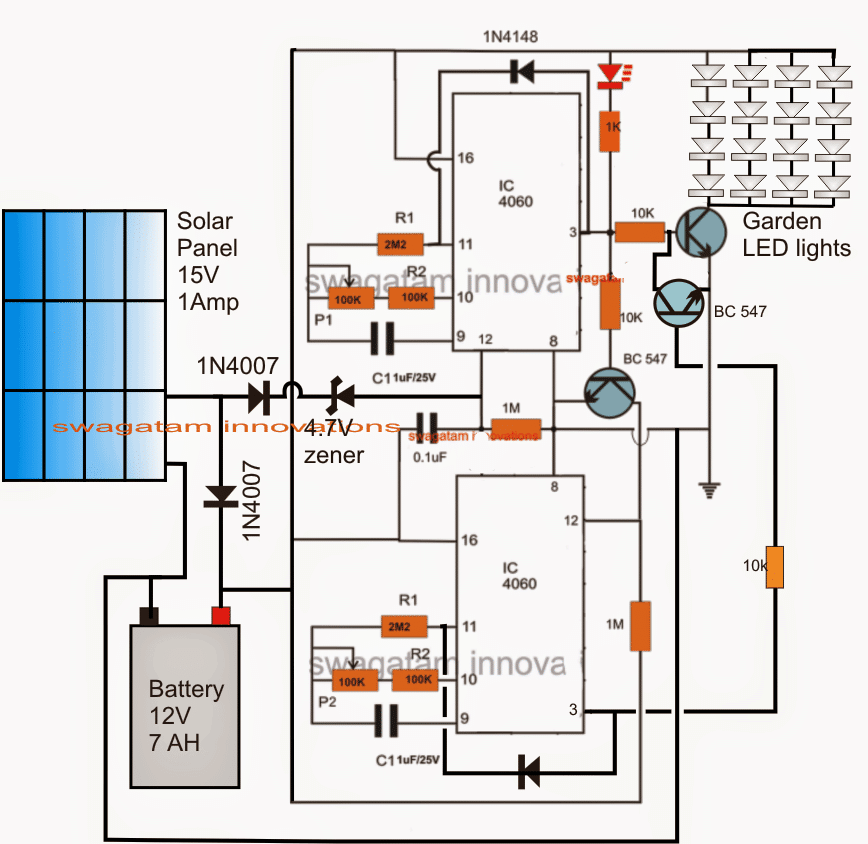
Referring to the proposed solar outdoor light circuit diagram, we see a couple of IC 4060 timer stages interlinked together to form a set of sequential programmable timers.
During day time when the solar panel is active, the connected battery is allowed to charge through it, while the 4060 timers are held inactive due to the presence of the positive voltage from the panel to pin12 of the upper 4060 IC.
When darkness sets in, depending upon the selection of the zener diode between the solar panel positive and pin12 of the upper 4060 IC, the voltage is brought down to zero allowing pin12 to get a resetting zero logic via the connected 1M resistor.
Once this happens the upper IC 4060 begin counting and after a predetermined delay set by its pin9 capacitor and pin10 pot, its pin3 goes high.
The BC547 connected with this pin3 now activates all the connected LEDs illuminating them after the desired period of time has elapsed. The 1N4148 diode connected across this pin3 and pin11 of the upper 4060 freezes the IC counting process and latches the LEDs permanently ON.
However, in this situation, the lower BC547 also gets triggered and resets pin12 of the lower IC 4060 which in turn begins counting, and identically after a set period of time determined by its own pin9 capacitor and pin10 pot values switches ON its pin3.
This high from pin3 of the lower IC 4060 latches itself due to the presence of the 1N4148 diode across its pin3 and pin11, and it also grounds the base of the LED BC547 driver such that all LEDs shut off.
The entire solar porch light timer circuit now latches in this position until the next morning, when the rising positive voltage from the solar panel yet again resets the upper IC pin12 and the entire circuit. The circuit stays inactive until dark.
The cycle thus keeps repeating as explained above.
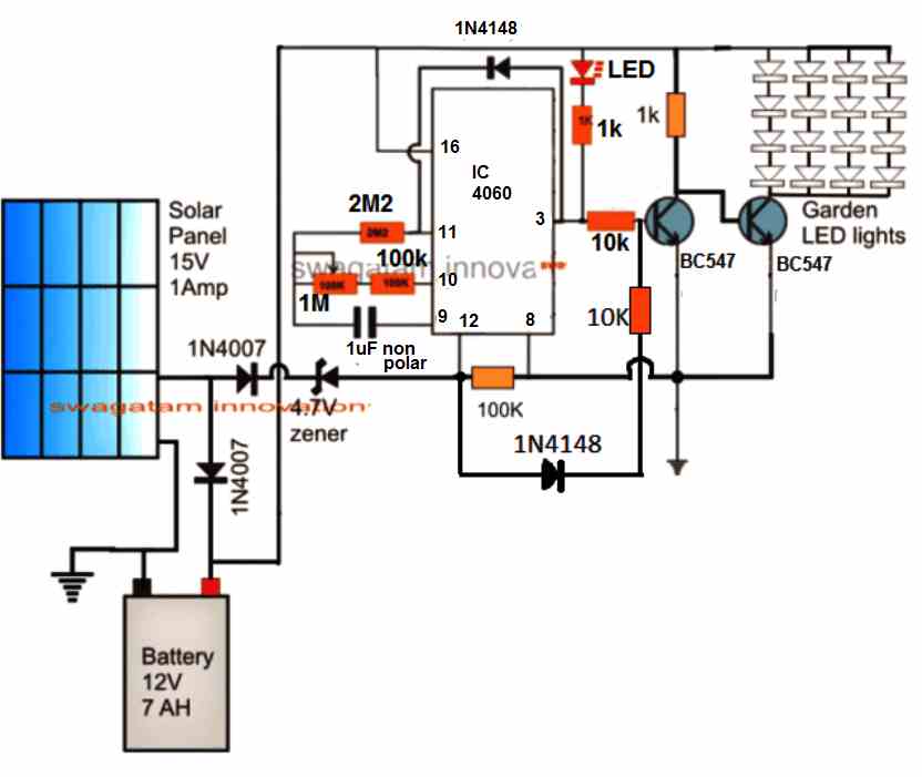
Single Adjustable Delay OFF Solar Timer Circuit
The above explained design can be simplified to obtain an adjustable delay switch OFF after the LEDs are switched ON in the evening.
Circuit Diagrams
Simple Porch Light Circuit using IC 555
The circuit design for the simple automatic porch light circuit is shown in the following figure.
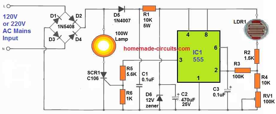
The system's sensor is the Light Dependent Resistor LDR1. The quantity of light falling on it determines its resistance; higher the light, lower will be the resistance. IC1 is utilised as a hysteresis level detector.
The 555 has 2/3Vcc and 1/4Vcc resistance levels built in. The output, pin 3, flips low whenever the voltage on pins 2 and 6 increases beyond 2/3Vcc, and high whenever the value falls under 1/4Vcc.
The preset RV1 is set such that it is turned on at the desired light level. A 10 second time constant is formed from R3 and C3.
This 10 second is the time it takes for the voltage on pins 2 and 6 to increase to 2/3Vcc, assuming C3 charges from 0 V, and it's added to help prevent unwanted triggering from things like approaching car headlights or kids with flashlights!
The circuit is powered by D1-D5, R1, and is controlled by D6.
Supply DC smoothing is provided by the capacitor C2.
The thyristor SCR1 controls the outside light. A thyristor had been adopted over a triac since it is easy to trigger and does not create radio frequency interference in this setup.
The downside of this technique is that it necessitates the use of a diode bridge (D1-D4), which should be correctly rated to handle the lamp current.
When testing early versions, it was discovered that mains transients may cause the light to flicker as soon as it approached the lower (switch on) threshold level.
D5, R1, C1, and C2 are all part of a thorough filter circuit. Any high frequency spikes on the mains supply will travel via D1 -D5 and be isolated from the supply's negative side by C1.
C1 has a lower impedance than R1 and hence has a lower impedance. C2 would try to discharge through R1 and the light circuit if the mains voltage failed or dropped for a few cycles. For this brief period, D5 and C2 keep supply high, with D5 being reversed biased.
The sensitive gate type C106D thyristor was employed in this simple porch light circuit. Between the SCR gate and cathode, you'll need an 0.8 V, with a gate current of 20 mA.
The output of the 555 is used to activate it. R5 and R6 create a voltage divider network, resulting in a cathode to gate voltage of roughly 2 V, which is adequate for effective triggering.
Whenever the 555 output drops low, R5 guarantees that the gate recovers to the very same voltage as the cathode, guaranteeing that the thyristor stays untriggered.
By lowering the value of R1 to 4k7 (2 W), the circuit may be changed for 115 V operation. The rest of the components are the same.
However, due to the lower supply voltage, the maximum wattage that may be switched is decreased to 250 W, with a maximum current of 2 A flowing via the diode bridge D1-D4 and thyristor SCR1.

Questions & Answers
Respected sir,
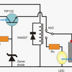
Please guide me to build a circuit for a solar powered intruder alarm of 50w which will be on 24 hrs and back-up by battery during night.
Hello Ritesh,
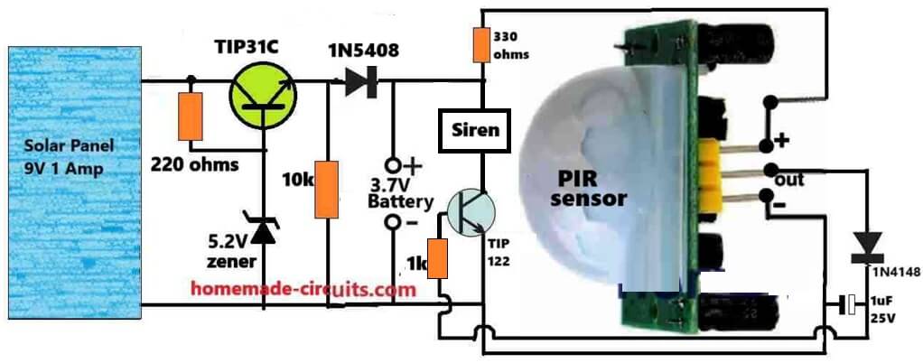
You can try the following circuit.
But for higher power, I think the battery should be a 12V battery and the solar panel should be rated at 18V, and the transistor zener diode must be a 15V zener. Also now the 330 ohms must be increased to 1k 1/4 watt..
Hello Swagatan
I’d like to be able to control my solar light string with a switch, instead of the built in darkness detector.
I have the: S14 LED solar light string
Solar Panel: 3W/5V
Li-ion 2000mAh3.7V
15 Bulbs
I have a room that doesn’t get a lot of afternoon light, and this is where I’ve put the light bulbs, but the solar panel is out in the sunshine. If I forget to take the cardboard off the panel, Well…
So can I put the wire that feeds the light bulbs directly to the battery wires, or is this a bad Idea? I’ll put my timer switch on the light feed wire.
I understand a little bit about circuitry, but not enough to figure out what part of the circuit board controls the darkness detector
Cardboard Joe in Pacific Grove
Hello Joseph,
If, assuming your darkness detector circuit also connects the battery directly with the LEDs then it is fine to replicate this and use a jumper wire to connect the battery directly with the LEDs.
I’m really enjoying my accent lights.
I’ve been looking around on the web trying to find the schematic for my BMC, but no luck. I really don’t like the way I’ve wired it, because I could kill the batteries. I’d like to attach a photo so maybe you could see a way where a could attach a jumper or d-solder something. Other wise I’m thinking of switching it out for the TP4056.
https://photos.app.goo.gl/7pFQkJ3Ln2AkLkiB6
Sorry, It could be extremely difficult to check and understand the circuit configuration from this image. The image should in the form of a schematic to enable proper understanding.
Okay Thanks, I’m going to mess with it a little bit, then go to plan “B”
Thank you
I’ll try it out.
Hi Swag,
How many LED’s can I use in this circuit?
Best Regards.
Hi Nelio,
It will basically depend on the transistor specs, for a TIP122 it can be around 30 watts of LEDs easily
If my calculations are correct, each LED is (P=U x I) = 3,5V x 0,02A (for white LED’s), that’s 0,07W per LED, eache row is 4 LED, which will give 0,28W per row. All 4 rows 1,12W.
That’s 107 rows of 4 LED each, total 428 LED’s…..
Uau!!!! That’s a lot of LED’s….
LOL
Best Regards.
Nélio Abreu
Yep, you are right, by using higher rated transistor and panel, you can increase it even more.
What changes do I need to do, in order to use a Li-Ion battery?
Best Regards.
Nélio Abreu
You can use a solar panel rated at around 4 V to 5 V higher than the battery, that’s all, but make sure the battery has a built in protection module.
I have a couple of questions to ask… What is that red diode on top of the circuit?? And also how do i adjust the time delay???
It's a red LED, P1 and P2 are used for adjusting the delay periods.
sir i made this circuit two to three times. I checked each and every point, but at first time relay get activated but after second third time relay not activated. I check test point. I get following observation.
Data: Supply 12.39 volt, Using relay at LED
1: I connect 1 led at pin 9 which blink with counting. at stops it continuous glow.
2: At the end, pin 3 get voltage 10.36v
3: At 10k left side 10.36v & right side 85.54mv
4: At base of transistor 85.55mv
5: Relay not activate.
6: 2nd IC not counting, it gets freeze.
Please help me i already made 3 pcb board but not successful.
please check below link
https://drive.google.com/file/d/0ByzJSqCugD_yR1dwc3lGeUZmbnc/view?usp=sharing
Ashok, if the supply voltage to the IC does not exceed 15V it is very unlikely to get faulty.
buy ICs of reputed brands like ST, MIC, intersil etc. for getting genuine response.
SIR I GET THE PROBLEM SOLVE, ACTUALLY IC GET FAULTY. i replace 4060 then circuit works fine. but after some time because of my miss handling again ic have same problem. again i replace another new one now its work fine.
Now my question is is there any procedure to avoid this parts fail? or how to check or purchase original parts.
Are these parts are fragile?
please help me for this so this project not goes to costly.
Ashok, do not connect anything at pin9, 10,11 as it may disrupt the normal functioning of the ICs.
connect LEd at pin14 or 15 03 13 of the IC, if it flashes will indicate the IC is counting.
For confirming the operational sequence, connect LEDs in series with all the transistor base resistors.
your statements are all contradicting
First if you apply voltage at pin12 of IC1 it'll never start counting which in turn will keep the lower IC also frozen.
you say that pin3 is showing 10V….that's impossible when pin12 is kept high.
So there may be something critically wrong in your design….pin12 of the top IC must not get the 12V supply otherwise it'll never initiate.
Sir as commented in above i already made this circuit 4 times but delay on gets failed because from red LED indicator voltage get supply to the base of transistor BC 547 ( marked in pic).
Ashok, that cannot happen because when switched ON the IC will reset and begin with a logic zero at its pin3, this zero logic will sink the LED voltage to ground level so that no voltage flows to pin11….and that's why the red LED would light up.
for confirming you can remove the red and check…..
Sir please check this image 4.bp.blogspot.com/-LWTCAHef9_I/VLjW36ME-vI/AAAAAAAAAKk/4Q59xls74T8/s1600/solar%2Bgarden%2Blight%2Bwith%2Btimer%2Bcircuit.png
hi swagatam
i need a circuit which will charge 12v 3ah battery during day on solar and automatically illuminate leds at no sun light. and it will off after 4 to 5 hrs. the purpose is to drive led strings for diwali decoration
Hi Shrikant, you can try the following simple design:
https://www.homemade-circuits.com/2013/03/simplest-automatic-led-solar-light.html
use 4 leds in series with the 12V battery, when the voltage drops below 12V, the LEd will automatically become dim and gradually become switched as the battery reaches 11V.